1 NC/Drive Machine Data 03.95
1.13 Coding of resolutions
1.13 Coding of resolutions
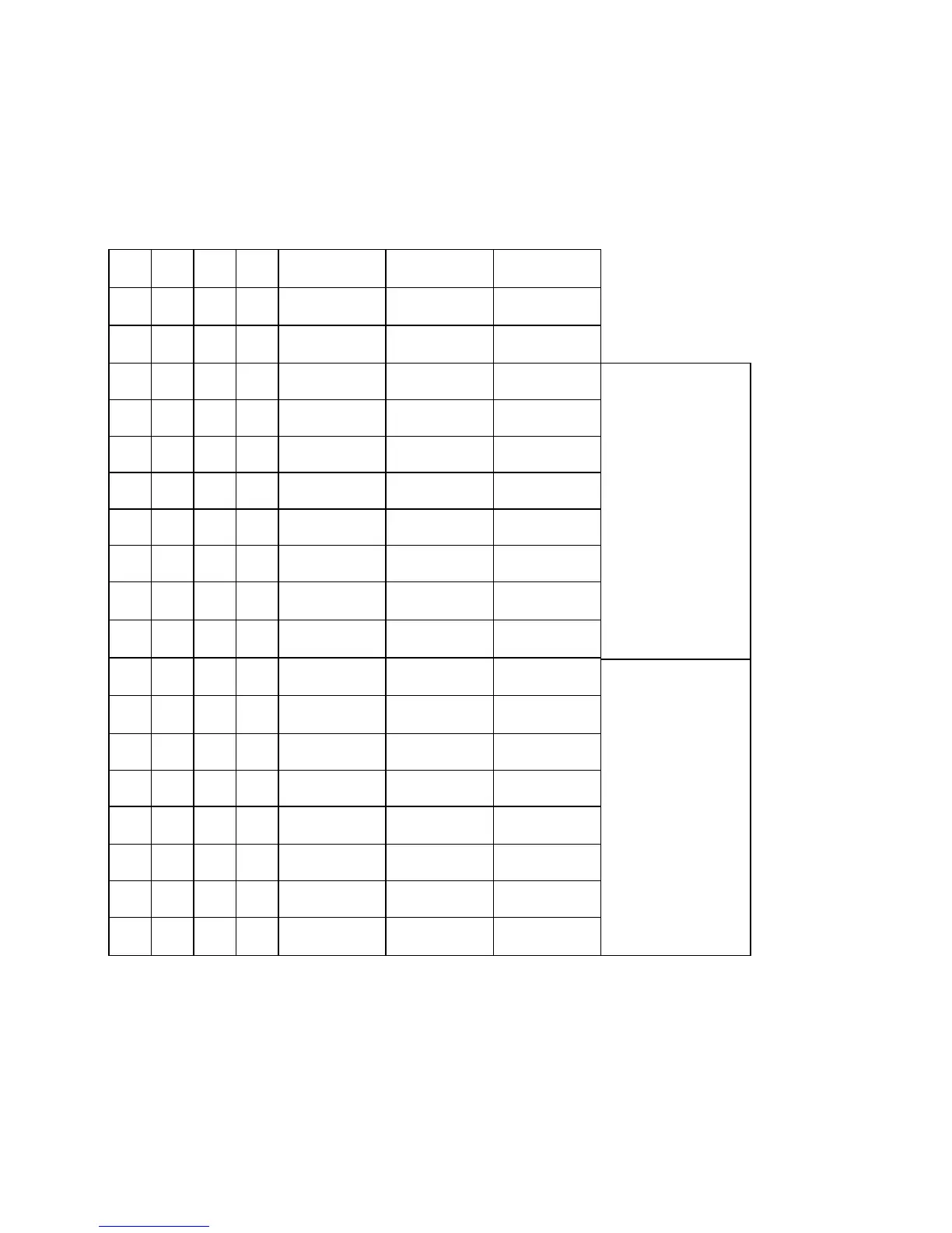
The table below shows the codes for the various resolutions. If illegal values are entered into
the machine data an alarm message 4 ”Input system impermissible” will ensue. NC MD 5002
bit 4 is used for designating the unit system. The metric input system G71 (bit 4=0) is the
initial setting.
Code table for resolutions
0100
= Standard machine data
Bit 7 Bit 6 Bit 5 Bit 4 Input resolution
Bit 7 Bit 6 Bit 5 Bit 4 Display resolution
Bit 3 Bit 2 Bit 1 Bit 0
Position control
resolution
0000
––––––––
10
-1
[mm]
[degrees]
0.5 x 10
-1
[deg]
1000
10
-2
[mm]
[degrees]
10
-2
[mm]
[degrees]
0.5 x 10
-2
[mm]
[deg]
0100
10
-3
[mm]
[degrees]
10
-3
[mm]
[degrees]
0.5 x 10
-3
[mm]
[deg]
1100
–––––––– ––––––––
2 x 10
-4
[mm]
[deg]
0010
10
-4
[mm]
[degrees]
10
-4
[mm]
[degrees]
0.5 x 10
-4
[mm]
[deg]
1010
10
-5
[mm]
[degrees]
10
-5
[mm]
[degrees]
0.5 x 10
-5
[mm]
[deg]
0110
–––––––– –––––––– ––––––––
1110
–––––––– –––––––– ––––––––
0001
––––––––
10
-1
[degrees] 0.5 x 10
-1
[deg]
1001
––––––––
10
-2
[degrees] 0.5 x 10
-2
[deg]
0101
10
-3
[inch]
[degrees]
10
-3
[inch]
[degrees]
0.5 x 10
-3
[inch]
[deg]
1101
10
-4
[inch]
[degrees]
10
-4
[inch]
[degrees]
0.5 x 10
-4
[inch]
[deg]
0011
–––––––– ––––––––
2 x
10
-5
[inch]
1011
10
-5
[inch]
[degrees]
10
-5
[inch]
[degrees]
0.5 x 10
-
5 [inch]
[deg]
0111
10
-6
[inch]
[degrees]
–––––––– ––––––––
1111
–––––––– –––––––– ––––––––
Metric
(degrees)
Inch
(degrees)
NC MD 5002
NC MD 1800*
NC MD 1800*
Note:
For more information on the topics of position control, input and display resolutions please
refer to the Installation Instructions Manual in the section entitled ”Axis (Analog) and Spindle
Installation”.
1–88
© Siemens AG 1992 All Rights Reserved 6FC5197- AA60
SINUMERIK 840C (IA)
 Loading...


