Spare parts/accessories
6.2 Fan/battery module
D4x5
60 Manual, 03/2007 Edition
6.2.3 Replace battery in the fan/battery module.
Procedure
Proceed as follows to replace the battery:
1. Gently press the fan/battery module backwards.
This detaches the module from its front latching device.
2. Tilt the fan/battery module forwards at an angle and pull out the plastic guide from the
recess of the control unit.
3. Remove the battery using a screwdriver (at the side) and disconnect the battery from the
module by unplugging the connector.
4. Connect the cable connector of the new battery to the mating connector in the fan/battery
module and push in the battery.
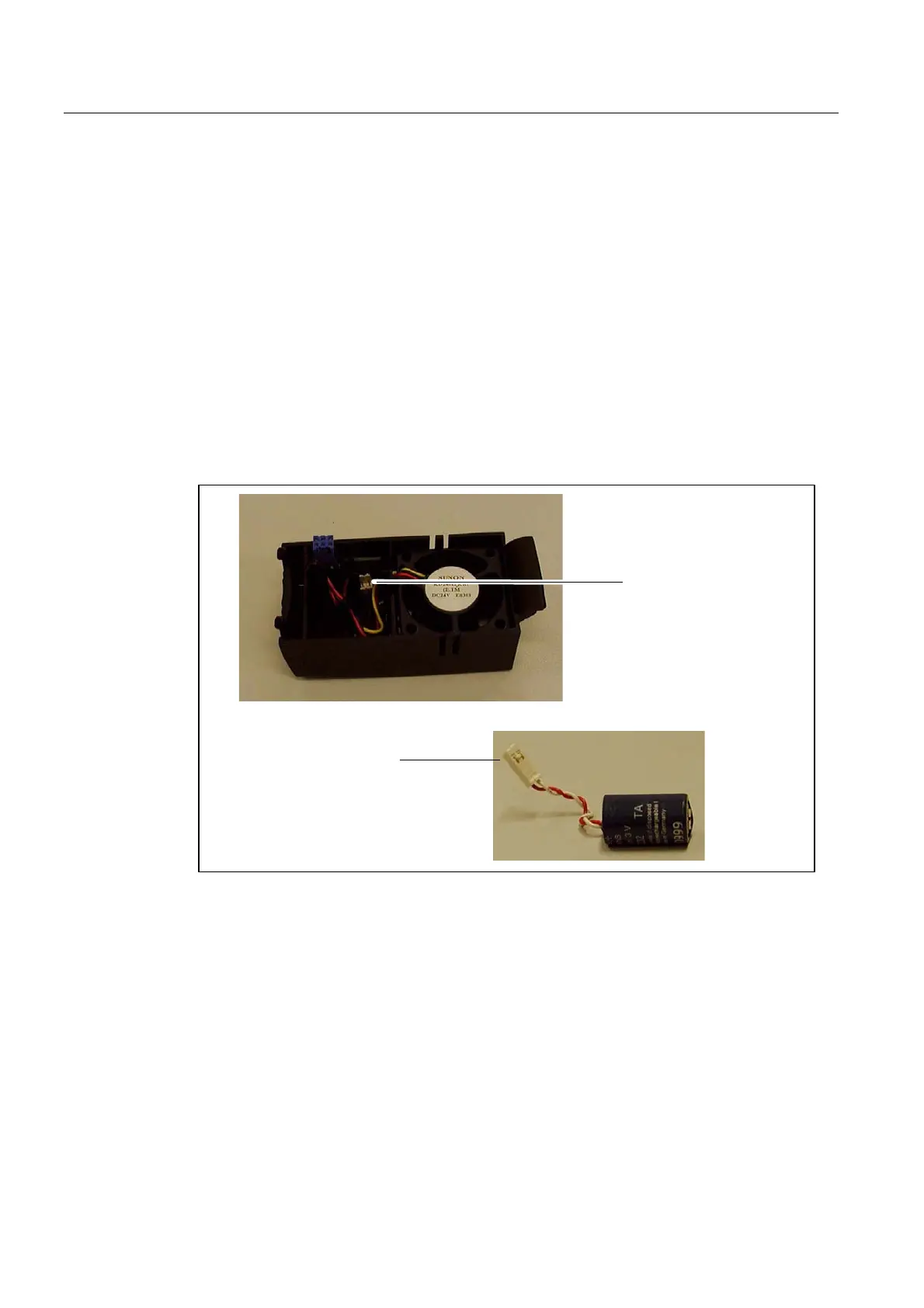
%DWWHU\FDEOHFRQQHFWRU
7HUPLQDOIRUEDWWHU\FDEOH
FRQQHFWRU
Figure 6-3 Battery replacement in the fan/battery module
5. Hold the fan/battery module at an angle to the front with the open side facing up (battery
visible).
6. Push the plastic guide into the cutout on the underside of the control unit.
7. Tilt the fan/battery module up until the front latching device snaps into place.
The electrical connection between the fan/battery module and the control unit is made
automatically.

 Loading...


