TM15 / TM17 High Feature Operating Manual
Commissioning Manual, 05/2009
45
Commissioning
3
3.1 Power-up
Once the terminal module is physically installed and connected electrically, power may be
applied to the unit.
DANGER
Ensure that installation and operation are in accordance with the instructions provided in
this Manual, and in accordance with the Safety Guidelines provided at the beginning of this
Manual. Failure to do so can result in serious injury or death.
Status LED (RDY) of module
The status of the module and the DRIVE-CLiQ interface are indicated by means of a
multicolored LED on the front panel of the TM. The individual colors are explained in the
following table. The error display is the same as that used on other SINAMICS components.
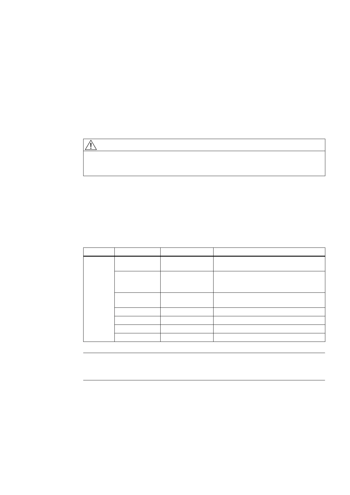
Table 3- 1 Module status
LEDs Color Status Description
- Off Electronics power supply outside the
permissible tolerance range.
Green Continuous light The component is ready for operation and
cyclic DRIVE-CLiQ communication is taking
place.
Orange Continuous light DRIVE-CLiQ communication is being
established.
Red Continuous light This component has at least one fault.
Green/Red Flashing 2 Hz Firmware is being downloaded.
Green/Orange Flashing 2 Hz Component detection: no faults detected.
READY
Red/Orange Flashing 2 Hz Component detection: fault(s) detected.
Note
Interruption of module power supply: If the power supply to the module is interrupted, all
outputs will switch to 0 V until synchronous communication resumes.
 Loading...


