Application tips
5.5 Other application examples
TM15 / TM17 High Feature Operating Manual
Commissioning Manual, 05/2009
63
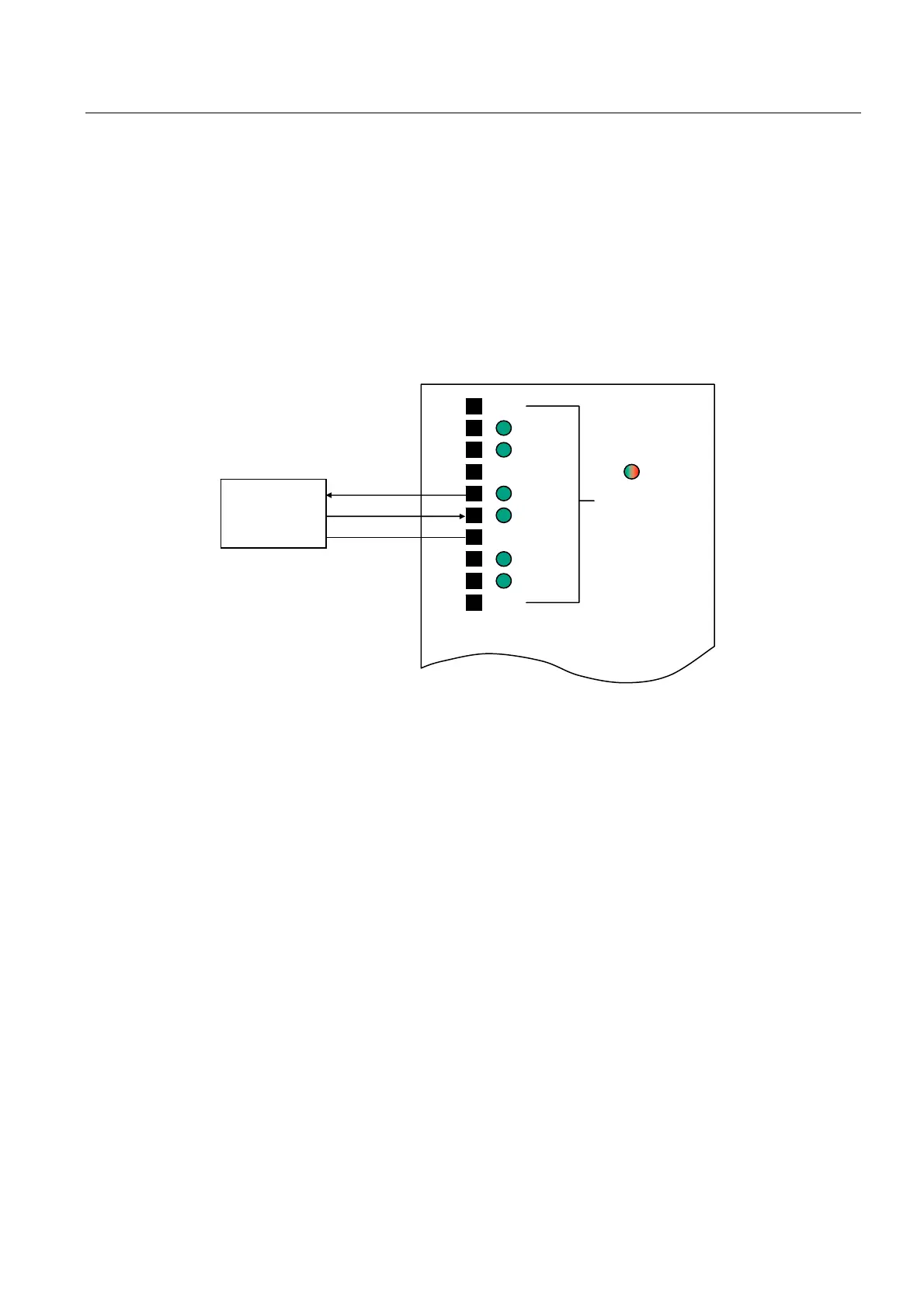
5.5.3 Connection of a proximity switch
The following figure shows an example of a proximity switch connection. Several "M"
(ground) terminals are available. In this example, the switch is supplied with 24 VDC via a
DI/O (DI/O 2 in the example below). This DI/O may also be used to supply multiple switches,
up to a current load of 500 mA per channel. (Typically, a 3-wire proximity switch requires
about 150 mA.)
If DI/O 2 is configured as an inverted output, a 24 V (high level) supply is applied after
system power up without being programmed. DI/O 3 must be configured as an input.
9'&
6ZLWFKRXWSXW
*URXQG
;
5'<
3UR[LPLW\
VZLWFK
',2
',2
',2
',2
',2
',2
0
0
0
0
70
Figure 5-6 Example: Proximity switch connected to TM17 High Feature
 Loading...


