Application tips
5.4 Input and output circuit
TM15 / TM17 High Feature Operating Manual
Commissioning Manual, 05/2009
59
5.4 Input and output circuit
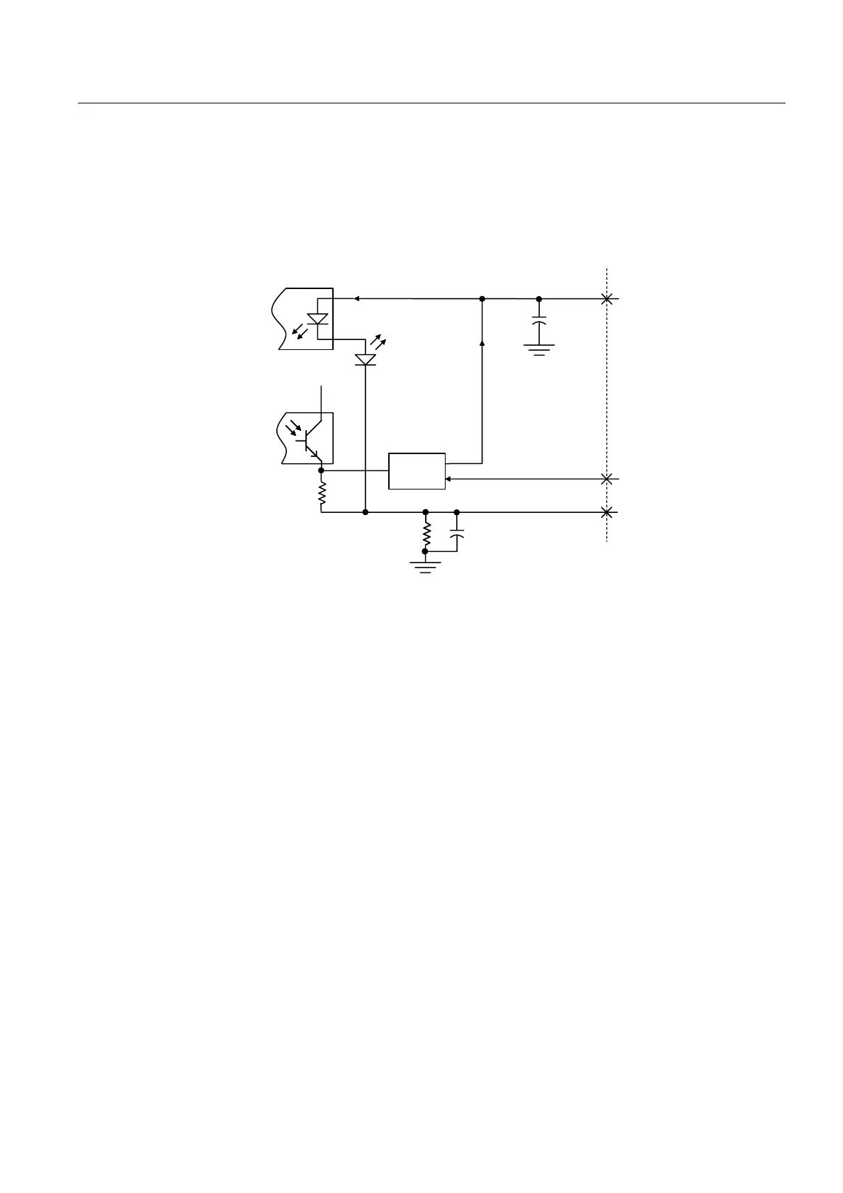
TM15
2XW
SXW
2XWSXW
RSWRFRXSOHU
,QSXW
RSWRFRXSOHU
,QSXW
&KDQQHO/('
0SLQ
2XWSXW
GULYHU
(QFORVXUH
(QFORVXUH
,2FKDQQHO
HLJKWSHUJURXS
/[SLQ
RQHSHUJURXS
0[SLQ
RQHSHUJURXS
)URP9'&,2YROWDJH
LH9'&IURP/[SLQ
9'&
QI
.
വ
QI0
വ
Figure 5-2 Input and output circuit - TM15
Grounding scheme
For TM15, the following are internally connected:
● Module power supply ground
● Logic ground
● TM chassis
The ground for the I/O power supply (terminals M1, M2, and M3) is capacitively coupled to
the three grounds indicated above.
If terminal M1, M2 or M3 is connected to one of the three grounds indicated above, isolation
for the associated group of I/O channels will be lost.
The I/O power supply ground (terminals M1, M2, and M3) must be connected to the
reference ground of the current source in order for their associated I/O channels to function.
 Loading...


