Application tips
5.4 Input and output circuit
TM15 / TM17 High Feature Operating Manual
60 Commissioning Manual, 05/2009
TM17 High Feature
2XWSXW
'&'&
FRQYHUWHUV
0RGXOH
,QSXW
&KDQQHO/('
2XWSXW
GULYHU
(QFORVXUH
,2FKDQQHO
HLJKWSHUJURXS
/[SLQ
RQHSHUJURXS
0SLQ
VL[SHUJURXS
7KH/('LVFRQWUROOHGE\WKH
)3*$7KH/('GLVSOD\UHIOHFWV
WKHVWDWXVRIWKH,2FKDQQHO
)3*$
9ROWDJH
9
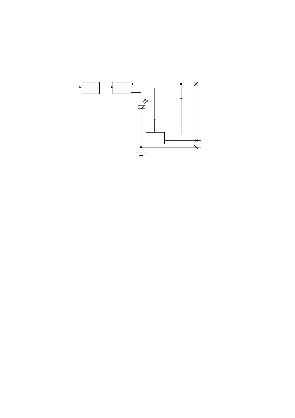
Figure 5-3 Input and output circuit - TM17
Grounding scheme
For TM17 High Feature, the following are internally connected:
● Module power supply ground
● Logic ground
● TM chassis
The ground of the I/O power supply is connected directly to the three grounds indicated
above.
The ground connections for the I/O of the TM17 High Feature and not isolated. The ground
of the I/O power supply (terminal M) must be connected to the reference ground of the
current source in order for their associated I/O channels to function.
 Loading...


