Technical data
6.2 System behavior
TM15 / TM17 High Feature Operating Manual
Commissioning Manual, 05/2009
77
T
in
= T
i
+ 1 x DRIVE CLiQ cycle; SINAMICS: T
i
≥ 125 µs
T
out
= T
o
+ 1 x DRIVE CLiQ cycle SINAMICS: T
o
≥ 125 µs
where T
i
and T
o
are isochronous PROFIBUS time parameters. The value of T
i
and T
o
depends on the other PROFIBUS nodes; you can read off the exact value from the "DP
Slave Properties" screen form in "HW Config". (In PROFINET screen "Properties - CBE20-
PN" of the device.)
Note
If the user program is executed in the servo-synchronous user task rather than the IPO
synchronous user task, the output signal is output one IPO cycle clock earlier.
Note
In order to operate the TM1X, the cycle time of the DRIVE CLiQ line must be at least 125 µs.
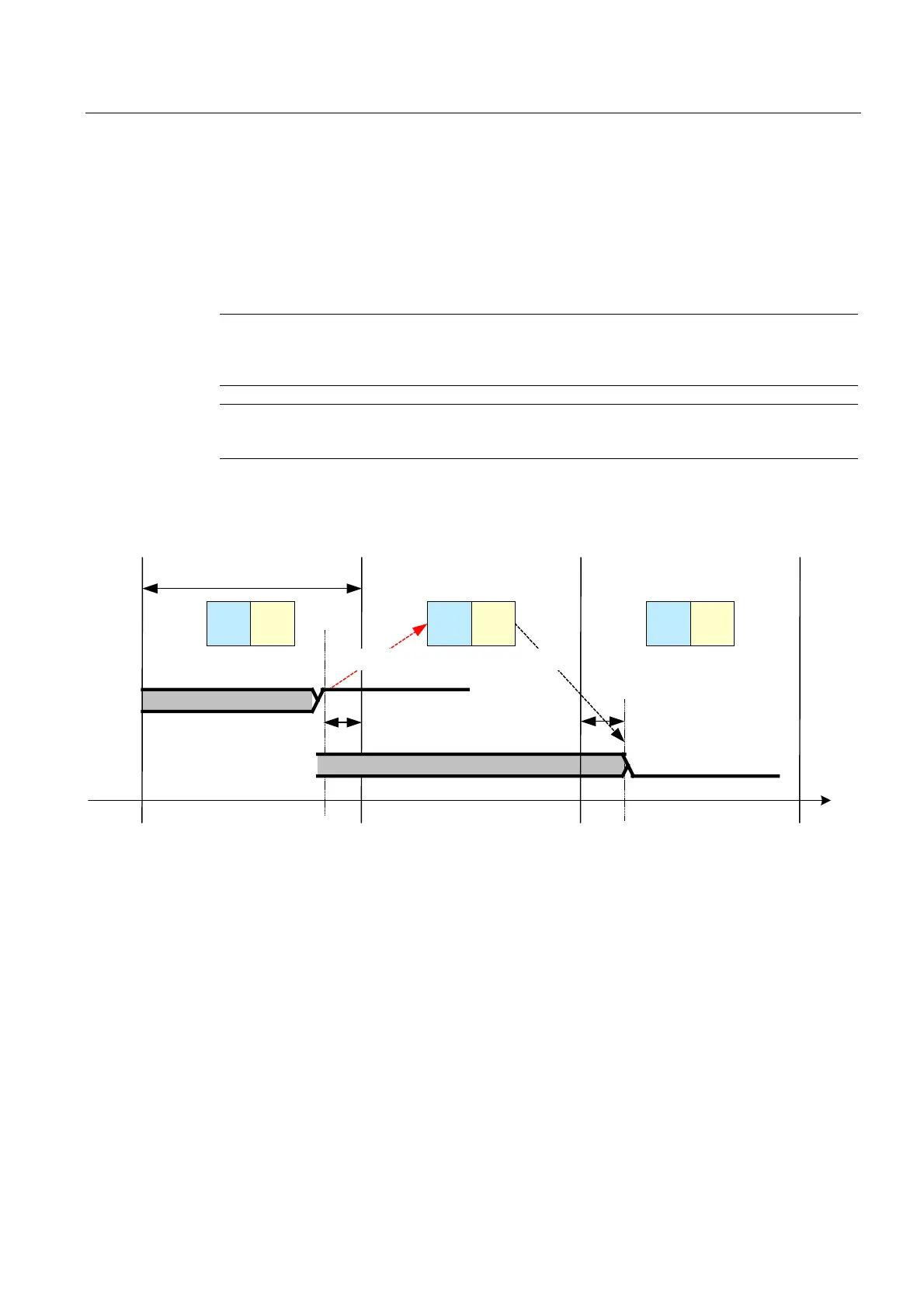
It is also possible to run a user program in the servo-synchronous task level. In this case, a
user-programmed response in position control cycle clock #3 (terminal-terminal response
time) is possible when there is a DI state change in position control cycle clock #1.
',
6HUYR
WDVN
,UUHOHYDQW
6HUYR
8VHU
SUR
JUDP
'2
6HUYR
8VHU
SUR
JUDP
6HUYR
8VHU
SUR
JUDP
,UUHOHYDQW
758(
LQ
7
RXW
7
/5
7
)$/6(
Figure 6-5 System behavior with digital inputs and outputs (TM15 and TM17 High Feature) with user program in the
servo-synchronous task level
 Loading...


