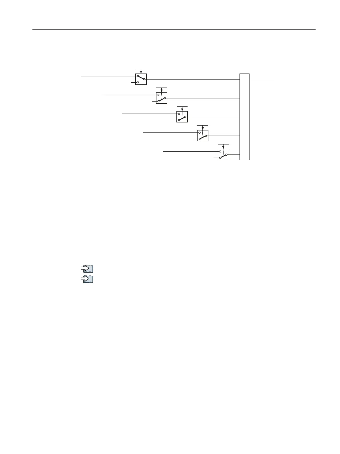
Signal "Safestate"
672DFWLYH
66DFWLYH
6/6DFWLYH
6',SRVLWLYHDFWLYH
6',QHJDWLYHDFWLYH
ุ
6DIHVWDWH
S
S
S
S
S
Figure 5-17 The Safetstate signal in the factory setting
You must set parameter p10039 in order to adapt the "Safestate" signal.
● STARTER: p10039 can only be accessed via the expert list
● Startdrive: p10039 can only be accessed via the parameter view
The test mode of the fail-safe output
Using its adjustable test mode, the inverter checks as to whether the fail-safe digital output
can be shut down.
The test mode is aligned according to the interconnection of the fail-safe digital output. For
test modes 2 and 3, you must adapt the appropriate wait time to your particular application.
Connecting the fail-safe digital output for a SINAMICS G120D (Page 97)
Connecting the fail-safe digital output for a SINAMICS G120 (Page 95)
Commissioning
5.12 Setting extended functions
Safety Integrated - SINAMICS G110M, G120, G120C, G120D and SIMATIC ET 200pro FC-2
Function Manual, 01/2017, FW V4.7 SP6, A5E34261271B AD 171

 Loading...


