Test mode 1
:DLWWLPHW
:
5HVSRQVHWLPHW
5
RI
WKHDFWXDWRU
W
:
W
:
W
:
W
:
6WDUW(QG
([SHFWHGVLJQDO
DW'2
7HVWVWRS)'2
'2
'2
W
W
)',
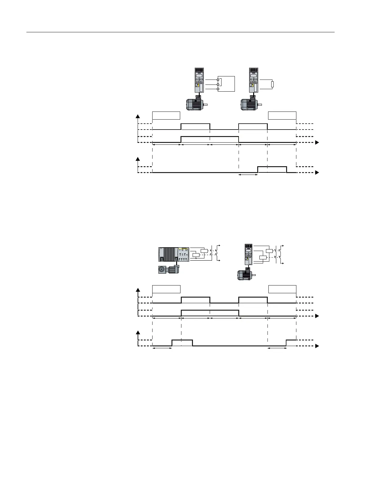
Figure 5-18 Expected response at digital output DO 2 for test mode 1
When testing the fail-safe digital output, the inverter switches the two digital outputs on and
off alternating - and evaluates the voltage signal at output DO 2.
Test mode 2
:DLWWLPHW
:
5HVSRQVHWLPHW
5
RI
WKHDFWXDWRU
W
5
W
:
W
:
W
:
W
:
6WDUW(QG
([SHFWHGUHVSRQVH
7HVWVWRS)'2
',
'2
'2
W
W
Figure 5-19 Expected response at the digital input for test mode 2
When testing the fail-safe digital output, the inverter switches the two digital outputs on and
off alternating, and evaluates the feedback via a digital input.
Commissioning
5.12 Setting extended functions
Safety Integrated - SINAMICS G110M, G120, G120C, G120D and SIMATIC ET 200pro FC-2
172 Function Manual, 01/2017, FW V4.7 SP6, A5E34261271B AD

 Loading...


