Test mode 3
:DLWWLPHW
:
5HVSRQVHWLPHW
5
RI
WKHDFWXDWRU
W
5
W
:
W
:
W
:
W
:
6WDUW(QG
([SHFWHGUHVSRQVH
7HVWVWRS
',
'2
'2
W
W
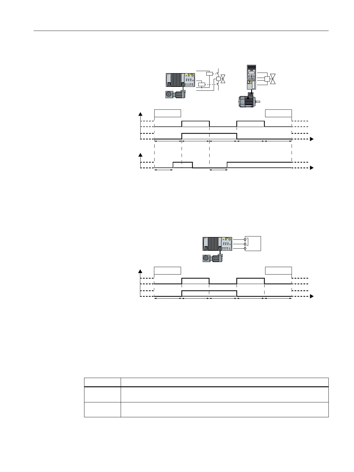
Figure 5-20 Expected response at the digital input for test mode 3
When testing the fail-safe digital output, the inverter switches the two digital outputs on and
off alternating, and evaluates the feedback via a digital input.
Test mode 4
6WDUW(QG
7HVWVWRS)'2
:DLWWLPHW
:
W
:
W
:
W
:
W
:
'2
'2
W
)',
Figure 5-21 Test mode 4
When testing the fail-safe digital output, the inverter switches the two digital outputs on and
off alternating.
SINAMIC G120D inverters monitor their transistor outputs using internal signals.
For SINAMICS G120, the connected fail-safe digital input F‑DI must monitor its input signals
for discrepancy.
Parameter Description
p10039 Safe State signal selection (factory setting: 0000 0001 bin)
Setting the signals for the "Safe State" signal.
p10042[0…
5]
F-DO signal sources (Factory setting: 0)
Setting the 6 signal sources for F-DO.
Commissioning
5.12 Setting extended functions
Safety Integrated - SINAMICS G110M, G120, G120C, G120D and SIMATIC ET 200pro FC-2
Function Manual, 01/2017, FW V4.7 SP6, A5E34261271B AD 173

 Loading...


