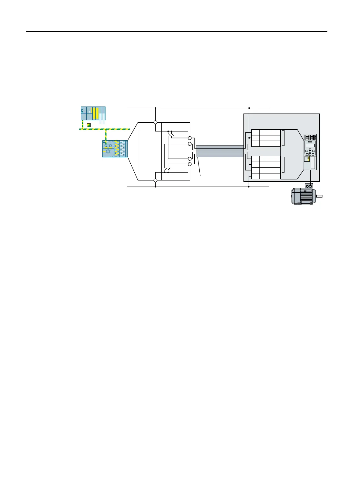
Components not in a control cabinet
A two-channel cable connection is required when connecting components not installed in a
control cabinet to a control cabinet. You must protect the cables between the I/O modules and
the inverter against cross and short-circuits - or ensure that a cross or short-circuit results in
a discrepancy error.
6DIHW\
IXQFWLRQ
6DIHW\
IXQFWLRQ
&RQWUROFDELQHW
&DEOHZLULQJURXWHG
LQVWHHOFRQGXLW
352),1(76DIHW\
9'&
0
(0)',)'2
352),VDIH
,0
;
;
;
;
)',
)',
',
',
',
',
',
',
',&20
6,1$0,&6*
&86
(7SUR
)&38
SINAMICS G120D requires a PP-switching fail-safe output.
DI COM1 Reference potential for digital inputs DI 0 and DI 2
Figure 4-27 Connecting PM-switching ET 200pro outputs using a SINAMICS G120 with CU250S‑2 as
example
Installing
4.4 Controlling via a fail-safe digital input
Safety Integrated - SINAMICS G110M, G120, G120C, G120D and SIMATIC ET 200pro FC-2
80 Function Manual, 01/2017, FW V4.7 SP6, A5E34261271B AD

 Loading...


