6DIHW\IXQFWLRQ
6DIHW\IXQFWLRQ
9'&
0
)'4[9'&$330
)',
)',
',
',
',
',
',&20
',&20
6
6,1$0,&6*
&8(
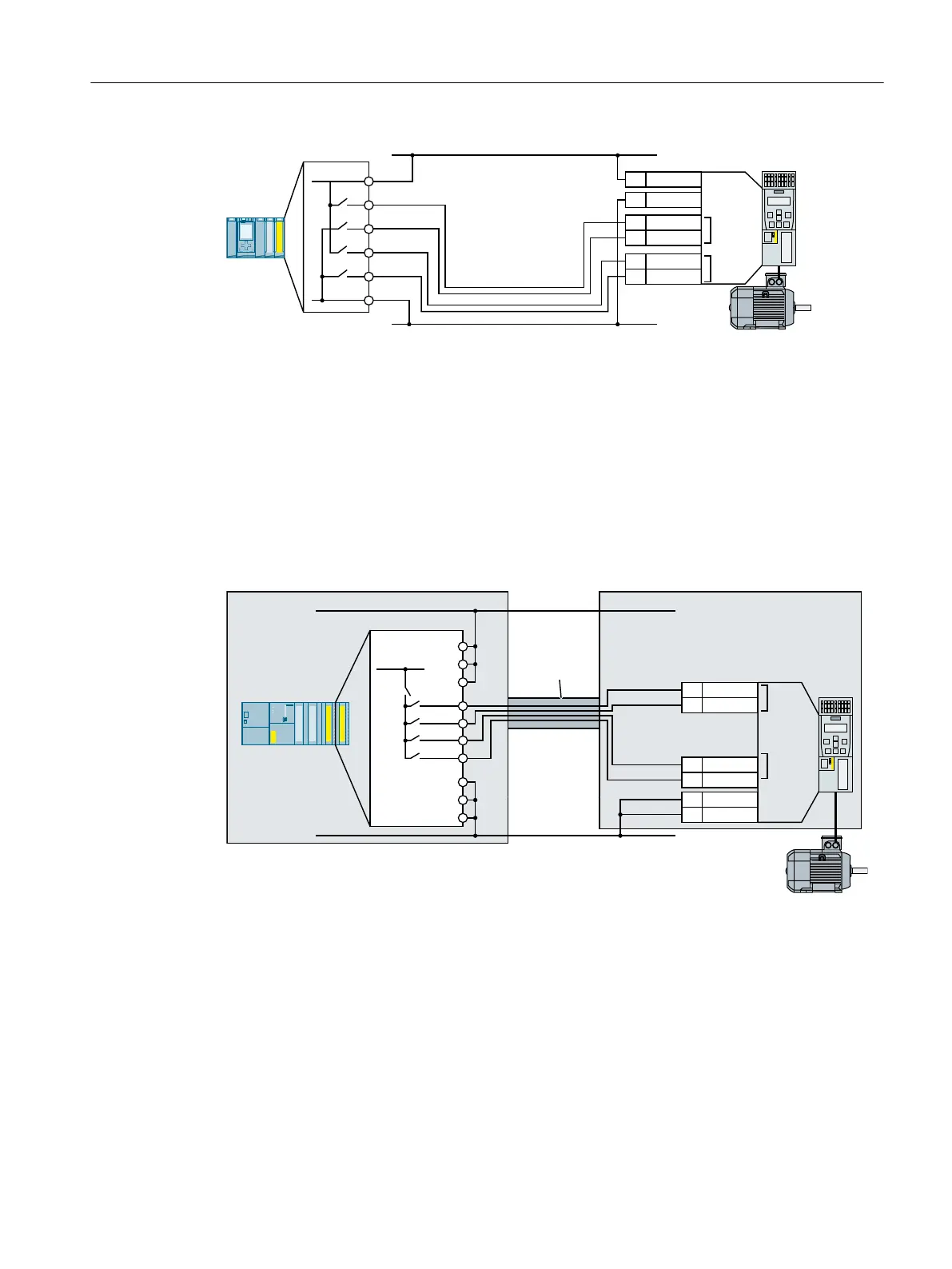
DI COM1 Reference potential for digital inputs DI 0 and DI 2
DI COM2 Reference potential for digital inputs DI 1 and DI 3
Figure 4-25 Connecting PM-switching S7-1500 outputs using a SINAMICS G120 with CU240E‑2 as
example
Components in separate control cabinets
A two-channel cable connection is required when installed in separate electrical cabinets. You
must protect the cables between the I/O modules and the inverter against cross and short-
circuits - or ensure that a cross or short-circuit results in a discrepancy error.
&DEOHZLULQJ
URXWHGLQ
VWHHOFRQGXLW
6DIHW\
IXQFWLRQ
6DIHW\
IXQFWLRQ
&RQWUROFDELQHW&RQWUROFDELQHW
9'&
0
)',
)',
',
',
',
',
',&20
',&20
6,1$0,&6*
&8(
9'&
60
6
Figure 4-26 Connecting the PP switching module SM326 using a SINAMICS G120 with CU240E‑2 as
example
Installing
4.4 Controlling via a fail-safe digital input
Safety Integrated - SINAMICS G110M, G120, G120C, G120D and SIMATIC ET 200pro FC-2
Function Manual, 01/2017, FW V4.7 SP6, A5E34261271B AD 79

 Loading...


