Technical data and characteristics
4.5 Dimension drawings
1PH7 induction motors (Machine tools)
184 Configuration Manual, (APH7W), 04/2009, 6SN1197-0AD72-0BP0
For motor Dimensions in mm (in) For dimensions of the shaft and terminal box foot installation,
see dimension drawing of 1PH718. and 1PH722. motors
type IM B3.
Terminal box type 1XB7...
Shaft
height
Type DIN a
1
b
1
c
1
e
1
f
1
h k k
1
...322 ...422 ...700 z α
IEC P N LA M T H LB –
p
1)
p
1)
p
1)
– –
1PH7, type IM B35, forced ventilation, air-flow direction DE to NDE
180 1PH7184
2)
1PH7184
2)
1PH7186
400
(15.75)
450
(17.72)
300
(11.81)
350
(13.78)
15
(0.59)
16
(0.63)
350
(13.78)
400
(15.75)
5
(0.20)
180
(7.09)
835
(32.87)
835
(32.87)
925
(36.42)
–495
(19.49)
–
–
560
(22.05)
–
–
–
4
8
45°
22.5°
225
1PH7224
1PH7226
1PH7228
550
(21.65)
450
(17.72)
18
(0.71)
500
(19.69)
5
(0.20)
225
(8.86)
–1100
(43.31)
1200
(47.24)
1290
(50.79)
595
(23.43)
645
(25.39)
–
680
(26.77)
822.5°
e
1
a
1
h
k
k
1
p
f
1
z x
c
1
b
1
G_DA65_EN_00152b
19(0.75)
1PH718 .
1PH722 .
1)
Maximum dimensions, depending on electrical version (terminal box type).
2)
See Order No. supplement for shaft heights 180 and 225.
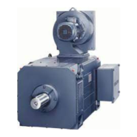
Figure 4-13 1PH7, type of construction IM B35, forced ventilation, direction of air flow DE-NDE

 Loading...


