Communication via PROFIBUS
Motion control with PROFIBUS
4-140
E Siemens AG, 2004. All rights reserved
SINAMICS S120 Installation and Start-Up Manual, 12/04 Edition
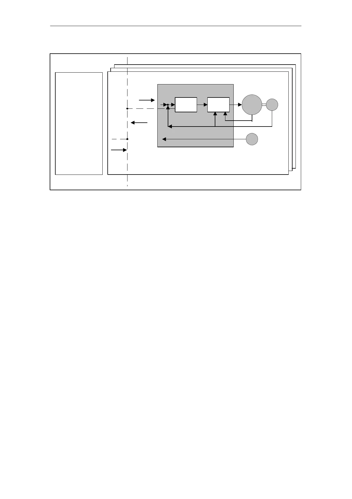
Position control loop
Direct
measuring system
(motor encoder)
Master with
function
“Motion control
with PROFIBUS”
taktsynchron_01.vsd
Speed
control
Power
control
G
G
Additional
measuring system
M
NSETP_A
G1_XACT1
Clock cycle
~
Indirect
measuring system
(motor encoder)
Fig. 4-16 Overview of “Motion control with PROFIBUS” (example: master and 3 slaves)
Structure of the data cycle
The data cycle comprises the following elements:
1. Global Control telegram
2. Cyclic part
– Setpoints and actual values
3. Acyclic part
– Parameters and diagnostic data
4. Reserved part
– Transmission of token
– For searching for a new node in the drive line-up
– Waiting time until next cycle

 Loading...


