Basic Information about the Drive System
Inputs/outputs
7-256
E Siemens AG, 2004. All rights reserved
SINAMICS S120 Installation and Start-Up Manual, 12/04 Edition
7.8.2 Digital inputs/outputs
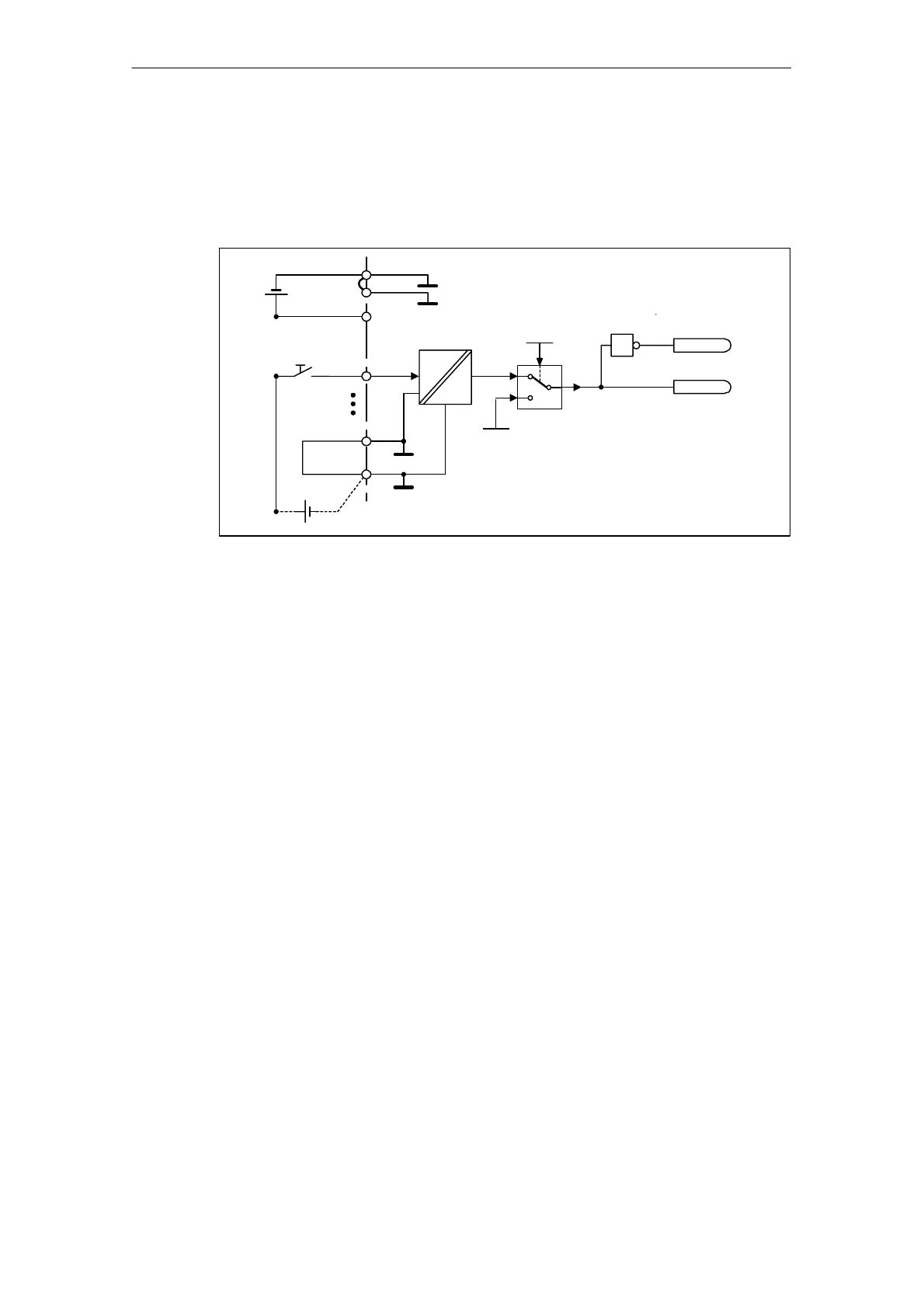
Digital inputs
digital_in.vsd
+24 V
X124.3
X124.1
DI 0X122.1
p0727.0
p0721.0
0
1
1
r0723.0
r0722.0
+
X122.5
X122.6
M1
M
M
X124.4
M
+
24 V
5 V
Fig. 7-10 Digital inputs: signal processing using DI 0 of CU320 as an example
Properties
S The digital inputs are “high-active”.
S An open input is interpreted as “low”.
S Fixed debouncing setting
Delay time = 1 to 2 current controller cycles (p0115[0])
S Availability of the input signal for further interconnection
– inverted and not inverted as a binector output
– as a connector output
S Simulation mode settable and parameterizable.
S CU 320: Isolation block by block, set by jumper.
– Jumper open floating
The digital inputs function only if a reference ground is connected.
– Jumper closed non-floating
The reference potential of the digital inputs is the ground of the Control Unit.
S Sampling time for digital inputs/outputs adjustable on CU320 (p0799)

 Loading...


