Commissioning
Initial commissioning using servo (booksize) as an example
3-55
E Siemens AG, 2004. All rights reserved
SINAMICS S120 Installation and Start-Up Manual, 12/04 Edition
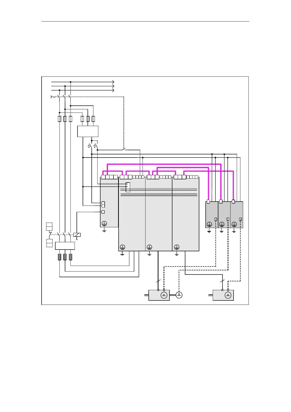
3.4.2 Component wiring (example)
The following diagram shows a possible component configuration and wiring op-
tion. The DRIVE-CLiQ wiring is highlighted in bold.
ibn_servo_verdrahtung.vsd
DRIVE–CLiQ
2 1
SH
2 1
SH
Line filter
Line reactor
DO
X124
X100
Control
Unit
320
SMC20
X500
X520
24 V DC
external
Line contactor
L1
L2
L3
Active
Line Module
X200
Single
Motor Module
X200
Single
Motor Module
X200
3 4
EP
DI
CU
ext.
24 V
4
4
Motor line
Encoder
cable
SMC20
X500
X520
SMC20
X500
X520
Fig. 3-2 Component wiring (example)
For more information on wiring, see the Equipment Manual.

 Loading...


