SINAMICS Safety Integrated (Booksize)
Overview of parameters and function diagrams
5-170
E Siemens AG, 2004. All rights reserved
SINAMICS S120 Installation and Start-Up Manual, 12/04 Edition
5.5 Overview of parameters and function diagrams
Parameter overview (see List Manual)
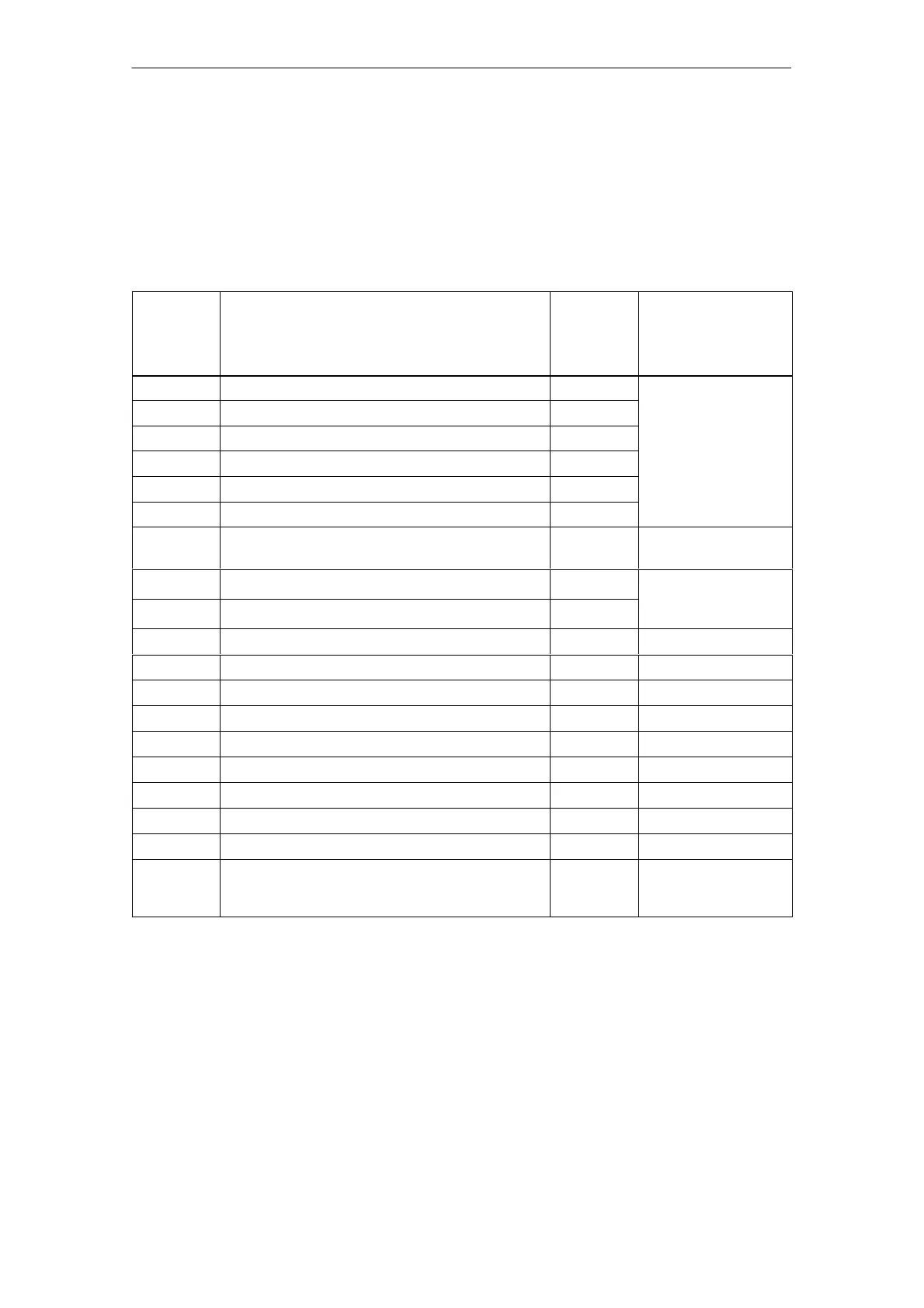
Table 5-3 Safety Integrated parameters
No.
Name No. Can be changed
Control
Unit
(CU)
Motor
Module
(MM)
in
p9601 Enable safety functions p9801
p9602 Enable safe brake control p9802
p9620 Signal source for safe standstill -
Safety Integrated
p9650 Safety Integrated tolerance time SGE changeover p9850
commissioning
0010 = 95
p9658 Transition period STOP F to STOP A p9858
p9659 Timer for forced checking procedure -
p9761 Password input - In every operating
mode
p9762 New password -
Safety Integrated
p9763 Confirm password -
commissioning
(p0010 = 95)
r9770[0...2] Version r9870[0...2] -
r9771 Shared functions r9871 -
r9772 Status r9872 -
r9773 Status (Control Unit + Motor Module) - -
r9774 Status (group safe standstill) - -
r9780 Monitoring clock cycle r9880 -
r9794 Cross monitoring list r9894 -
r9795 Diagnostics for STOP F r9895 -
r9798 Safety Integrated actual checksum SI parameters r9898 -
p9799 Safety Integrated specified checksum SI
parameters
p9899 Safety Integrated
commissioning
(p0010 = 95)

 Loading...


