Basic Information about the Drive System
Inputs/outputs
7-257
E Siemens AG, 2004. All rights reserved
SINAMICS S120 Installation and Start-Up Manual, 12/04 Edition
Function diagram for digital inputs/outputs (see List Manual)
S 2100 Digital inputs, electrically isolated (DI 0 ... DI 3)
S 2120 Digital inputs, electrically isolated (DI 4 ... DI 7)
S 9100 Digital inputs, electrically isolated (DI 0 ... DI 3)
S 9550 Digital inputs, electrically isolated (DI 0 ... DI 3)
S 9552 Digital inputs, electrically isolated (DI 4 ... DI 7)
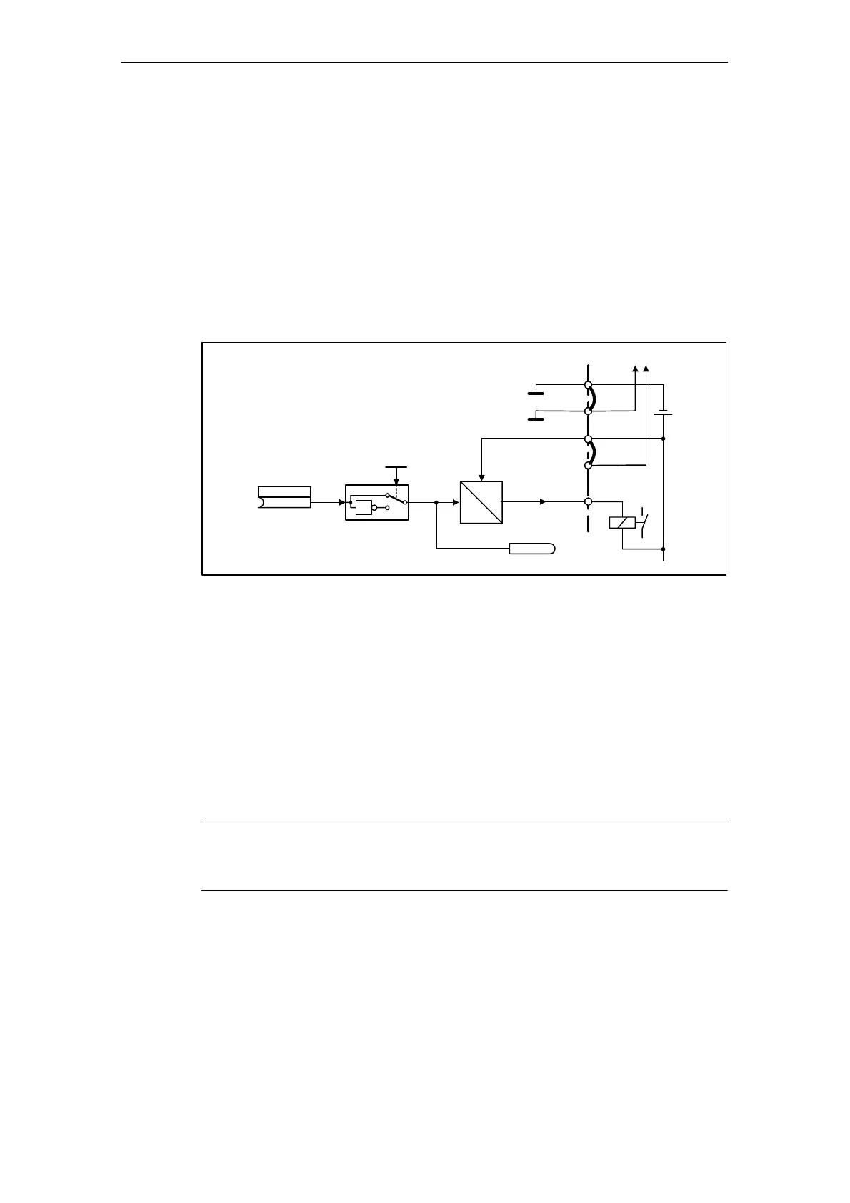
Digital outputs
digital_out.vsd
DO 0
r4047.0
p4030 (0)
p4048.0
1
0
1
24 V
5 V
X481.5
X424.4
X424.2
+
X424.3
Next supply
X424.1
+24 Vext
+24 Vext
Mext
Mext
Fig. 7-11 Digital outputs: signal processing using DO 0 of TB30 as an example
Properties
S Separate power supply for the digital outputs.
S Source of output signal can be selected by parameter.
S Signal can be inverted by parameter.
S Status of output signal can be displayed
– as a binector output
– as a connector output
Note
Before the digital outputs can function, their own electronics power supply must be
connected.
Function diagram overview (see List Manual)
S 9102 Electrically isolated digital outputs (DO 0 to DO 3)
S 9556 Digital relay outputs, electrically isolated (DO 0 and DO 1)

 Loading...


