SINAMICS Safety Integrated (Booksize)
Safe standstill (SH)
5-155
E Siemens AG, 2004. All rights reserved
SINAMICS S120 Installation and Start-Up Manual, 12/04 Edition
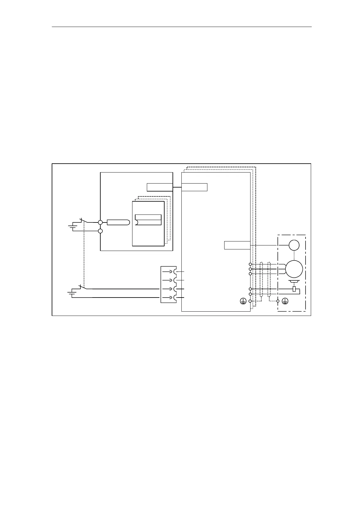
Terminals for “Safe standstill”
The “Safe standstill” function is selected/deselected separately for each drive via
the terminals on the Control Unit and Motor Module.
S Control Unit
The required input terminal for “Safe standstill (SH)” is selected via the BICO
interconnection (BI: p9620).
Digital input DI 0 ... DI 7 on the Control Unit can be used as a signal source.
S Motor Module
The input terminal for “Safe standstill (SH)” is terminal “EP” (“Enable pulses”).
Both terminals must be activated simultaneously, otherwise a fault is output.
safety_sh.vsd
r0722.x
Control Unit
DRIVE–CLiQ
Temp +
X21/X22
Temp –
EP M
EP +24 V
U2
V2
BR+
W2
BR–
DI x
M
BI:
p9620
Motor Module
DRIVE–CLiQ
DRIVE–CLiQ
X132.x
Monitoring channel
Motor Module
~
M
3
G
X122.x
Monitoring channel
Control Unit
4
3
2
1
Fig. 5-1 Terminals for “Safe standstill”
Grouping drives
To ensure that the function can be triggered simultaneously for more than one
drive, the terminals for the corresponding drives must be grouped together as fol-
lows:
S Control Unit
By connecting the binector input to the joint input terminal on the drives in one
group.
S Motor Module
By wiring the “EP” terminal on the individual Motor Modules in the group.

 Loading...


