Basic Information about the Drive System
BICO technology: interconnection of signals
7-238
E Siemens AG, 2004. All rights reserved
SINAMICS S120 Installation and Start-Up Manual, 12/04 Edition
Table 7-3 Connectors
Abbrevia-
tion and
symbol
Name Description
CI
Connector Input
Connector Input
(signal sink)
Can be interconnected to a connector out-
put as source.
The number of the connector output must
be entered as a parameter value.
CO
Connector Output
Connector Output
(signal source)
Can be used as a source for a connector
input.
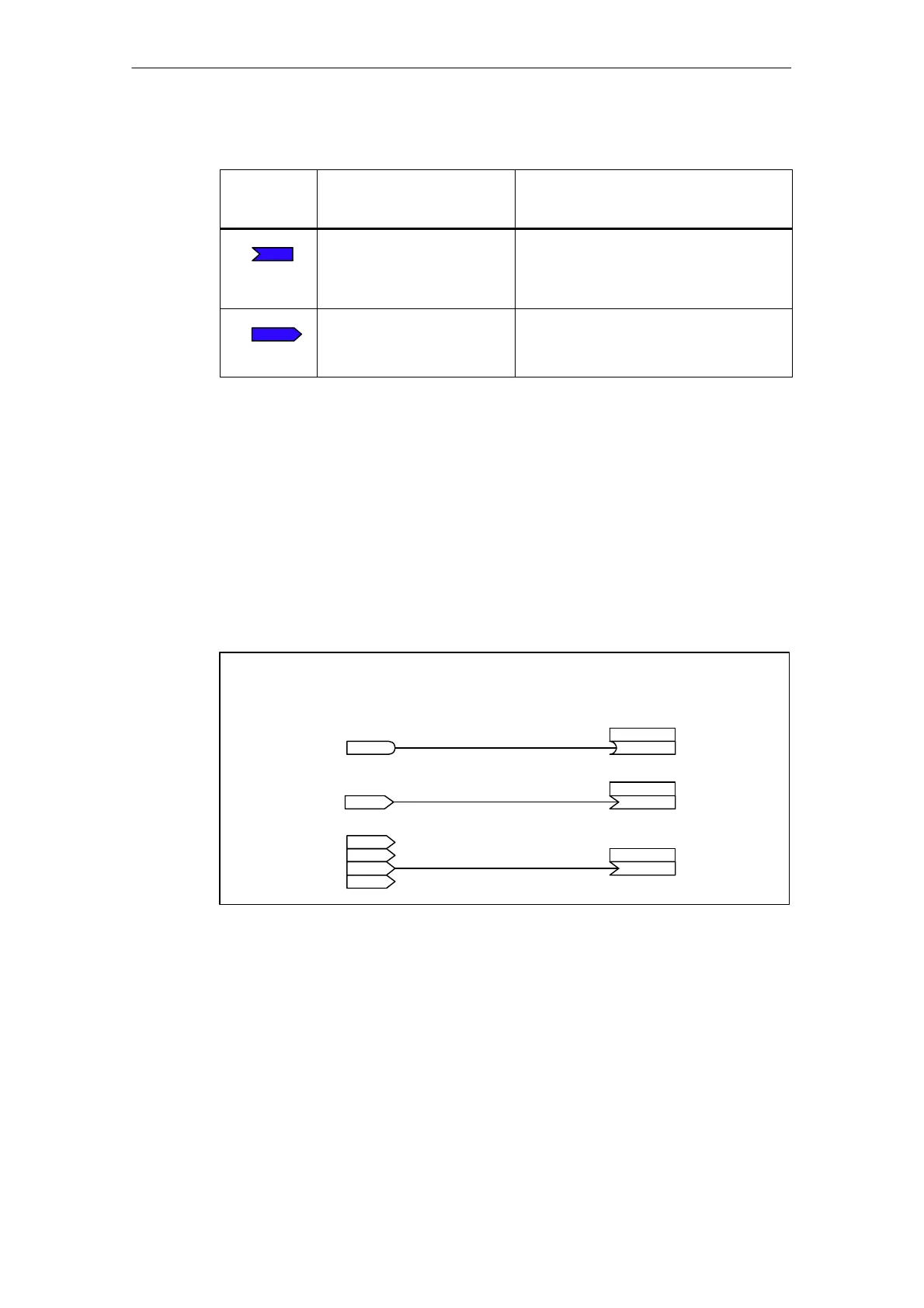
Interconnecting signals using BICO technology
To interconnect two signals, a BICO input parameter (signal sink) must be as-
signed to the desired BICO output parameter (signal source).
The following information is required in order to connect a binector/connector input
to a binector/connector output:
S Binectors: Parameter number, bit number and drive object ID
S Connectors with no index: Parameter number and drive object ID
S Connectors with index: Parameter number and index and drive object ID
bico_1.vsd
BO: Binector output
CO: Connector output
Signal source
BI: Binector input
CI: Connector input
Signal sink
pxxxx.y
722.0
BI
r0722.0
BO
r0037
CO (with index)
pxxxx.y
37[2]
CI
Index [0]
r0037
r0037
[1]
[2]
r0037
[3]
r0036
CO (with no index) pxxxx.y
36
CI
Fig. 7-5 Interconnecting signals using BICO technology

 Loading...


