Preparations for Commissioning
Rules for wiring with DRIVE-CLiQ
2-34
E Siemens AG, 2004. All rights reserved
SINAMICS S120 Installation and Start-Up Manual, 12/04 Edition
Note
You can call up the “Topology” screen in STARTER to change and/or check the
DRIVE-CLiQ topology for each drive unit.
Optional rules:
S The DRIVE-CLiQ cable from the Control Unit must be connected to X200 on
the first booksize power section or X400 on the first chassis power section.
S The DRIVE-CLiQ connections between the power sections must each be
connected from interface X201 to X200 / from X401 to X400 on the follow-on
component.
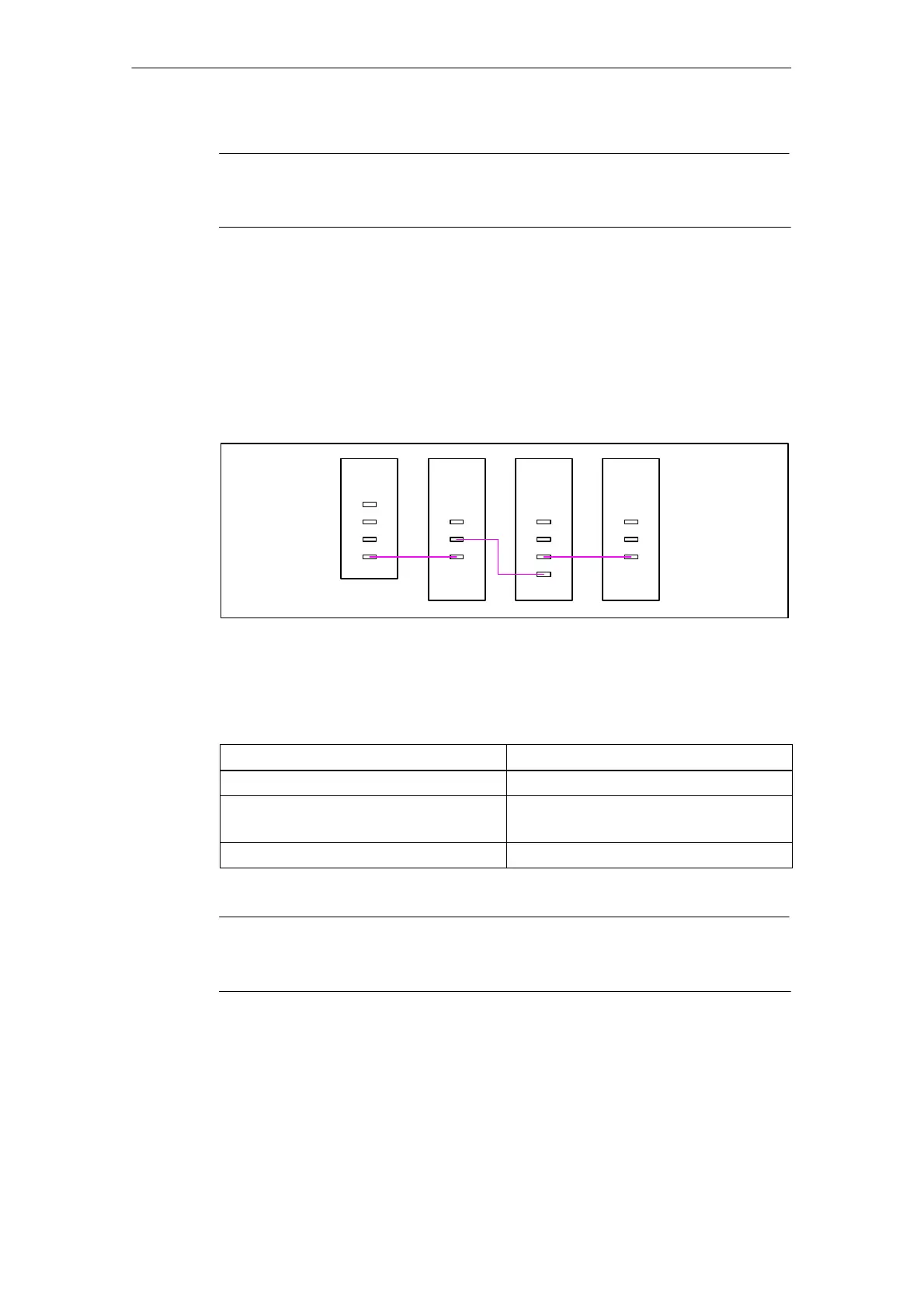
topologie_1.vsd
CU
320
X100
X101
X102
X103
Single
Module
X202/X402
X201/X401
X200/X400
Double
Module
Single
Module
X202/X402
X201/X401
X200/X400
X202
X201
X200
X203
Motor
Motor
Motor
Fig. 2-3 Example: DRIVE-CLiQ line
S The motor encoder must be connected to the associated Motor Module.
Table 2-4 Motor encoder connection
Component
Motor encoder connection
Single Motor Module (booksize) X202
Double Motor Module (booksize) S Motor terminal X1: encoder to X202
S Motor terminal X2: encoder to X203
Single Motor Module (chassis) X402
Note
If an additional encoder is connected to a Motor Module, it is automatically
assigned to this drive as encoder 2.
S The Voltage Sensing Module must be connected to the associated Active Line
Module. The Voltage Sensing Module is installed in the Active Interface Module
(chassis).

 Loading...


