Connection of the Components
5.3 Line Modules Interfaces Description
Guide for the SINUMERIK 840D sl machine configuring
Manual, 07/2006 Edition, 6FC5397-6CP10-0BA0
5-19
5.3.2.4 Active Line Module X21 EP Terminals
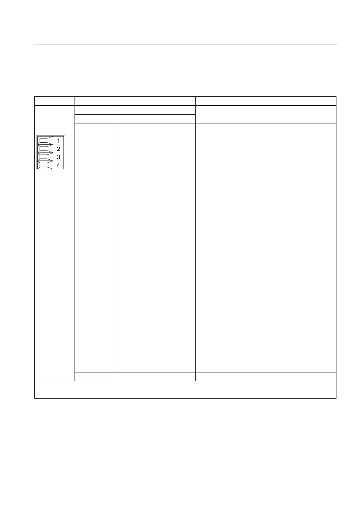
Table 5-3 X21 terminal block
Terminal Designation Technical data
1 Reserved, do not use!
2 Reserved, do not use!
3 EP +24 V (Enable Pulses) Enable EP control input:
The activation, and thus the enable of the boost
converter and the regenerative operation, is achieved by
placing a voltage 24 VDC (High level) at the -X21:3 (EP
+24 V) terminal.
The supply voltage must be provided from an external
power supply. The -X21:4 (EP M) terminal is used as
reference ground for the external supply voltage.
Disable EP control input:
If the EP control input is not enabled (Low level), the
boost converter for the Active Line Module must be
deactivated (Smart Mode). The diode bridge remains
active, the DC link operates unregulated and the DC link
voltage reduces to the value U
DC link
= U
N
*1.35. The
regenerative function is also disabled.
Signal propagation delays:
Enable: switch from Low to High level in 100 µs
Disable: switch from High to Low level in 1000 µs
Notice:
For the case that the EP control input is disabled and
the boost converter is non-operational, the CD link
remains connected with the supply voltage via the diode
bridge / precharging resistors. Energy continues to be
loaded into the DC link. If this is to be avoided, a line
contactor, for example, can be used.
Warning:
Before the main power switch is used to switch off the
drive group, the EP function (–X21:3 (+ 24 V) and –
X21:4 (M) connections on the Active Line Module must
be disabled, for example, using a leading (≤ 10 ms)
disabling auxiliary switch on the main power switch.
Note :
Without enable of the EP control input, no enable of the
line contactor On/Off control function will be performed.
4 EP M (Enable Pulses) Reference potential for the -X21:3 terminal
Max. connectable cross-section: 1.5 mm
2
Type: Screw terminal 1

 Loading...


