Connection of the Components
5.3 Line Modules Interfaces Description
Guide for the SINUMERIK 840D sl machine configuring
Manual, 07/2006 Edition, 6FC5397-6CP10-0BA0
5-21
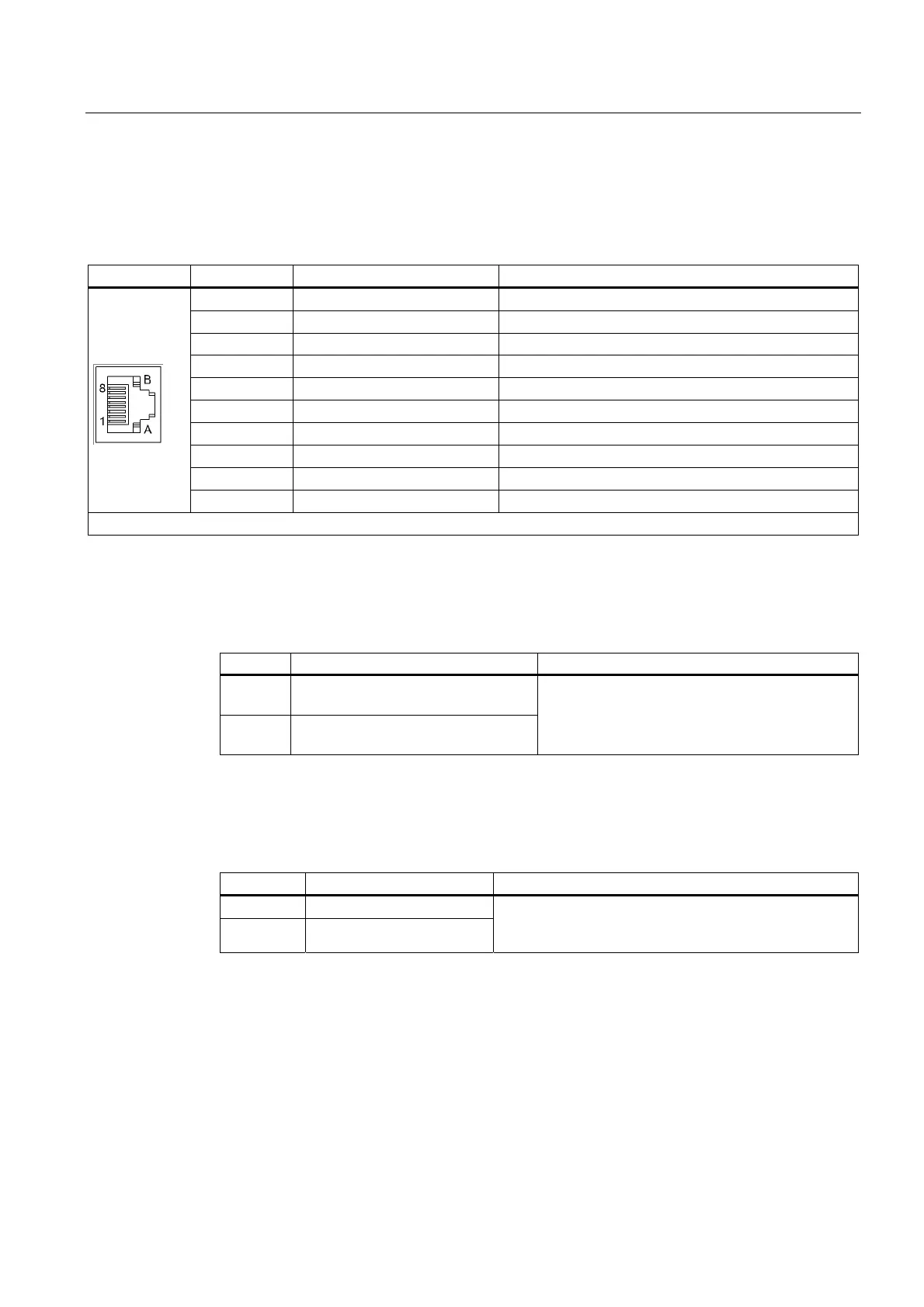
5.3.2.6 X200-X202 DRIVE-CLiQ interfaces
Table 5-5 DRIVE-CLiQ interface X200-X202
PIN Signal name Technical specifications
1 TXP Transmit data +
2 TXN Transmit data -
3 RXP Receive data +
4 Reserved, do not use
5 Reserved, do not use
6 RXN Receive data -
7 Reserved, do not use
8 Reserved, do not use
A + (24 V) 24 V power supply
B M (0 V) Electronics ground
Blanking plate for DRIVE-CLiQ interface: Molex, order number: 85999-3255
5.3.2.7 24 V busbar
Busbar Designation Remarks
+ 24 VDC power supply busbar, plus
pole
M 24 VDC power supply busbar, ground
pole
Two connection straps on the distribution busbar
can be used to pass the voltage potential to
neighboring components.
5.3.2.8 Active Line Module DC Link Busbar
Busbar Designation Remarks
DCP DC link plus pole
DCN DC link minus pole
Two connection straps on the distribution busbar can be
used to pass the voltage potential to neighboring
components.
The Active Line Module is controlled using the -X21 terminal block, terminal 3 and 4 (EP),
and using DRIVE-CLiQ at the -X200/202/203 terminal block. The detailed function
description for the individual signals and control/status words is contained in the
SINAMICS S Parameter Manual.
Once the Active Line Module has been switched on, the DC link has been precharged and
the boost converter has attained the setpoint of the DC link voltage, the unit uses the r0863.0
parameter to signal the "infeed ready" status. The signal must then be connected by
parameter for enabling the Motor Modules. This ensures that the Motor Modules can be
started only when the DC link is operating correctly. The Motor Modules will be disabled
immediately in case of faults, etc.

 Loading...


