Connection of the Components
5.3 Line Modules Interfaces Description
Guide for the SINUMERIK 840D sl machine configuring
Manual, 07/2006 Edition, 6FC5397-6CP10-0BA0
5-27
Note
For operation, ground must be attached to the -X21:3 24 VDC terminals and the -X21:4
terminals. When removed, pulse inhibit is activated, feedback is deactivated and the bypass
relay drops out. If the Line Module is not disconnected from the network when the EP
terminal is deactivated (e.g. a main contactor is not installed), the DC link remains charged.
Notice
If the main power switch is used to switch off a running drive group, the voltage at terminal -
X21:3 (EP +24 V) and -X21:4 (EP M) must be interrupted beforehand. This can be achieved,
for example, with a leading (≥10 ms) disconnecting auxiliary contact.
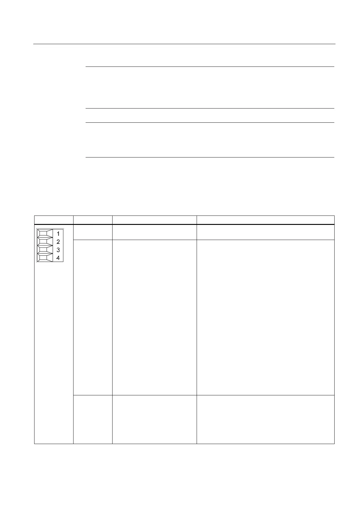
5.3.3.5 X22 terminals: smart line module
Table 5-9 Terminal block X22
Terminal Designation Technical data
1 24 V power supply 24 VDC electronic power supply (24 VDC, 100 mA)
for the control of the X22.2 and 3 digital inputs.
2 DI: Disable Regeneration DigitalinputDisable Enable Disable control input:
Enable and thus activate the regenerative capability of
the Smart Line Module when the Disable control input
is open (Low level).
Disable Disable control input:
If the Disable control input is not enabled (High level),
the regenerative capability of the Smart Line Module is
deactivated.
No energy from the DC link can be fed into the supply
system. The energy may need to be removed using
braking resistors.
Note:
The Disable control input may not be operated during
running operation. The preselection should be made
using a fixed wire jumper.
Notice:
In the case that the Disable control input has the High
level and thus the regenerative capability is
deactivated, the DC link remains connected with the
energy supply system using the diode bridge /
precharging resistors.
No electrical isolation exists.
3 DI: Reset DigitalinputReset
If this input is jumpered with the electronic ground or
the input is controlled from an external PLC, the
internal fault memory will be reset (a negative edge
resets the fault). If the fault is still present, no reset will
be performed. The reset is also possible by canceling
the external 24 VDC (-X24).

 Loading...


