EasyManuals Logo

Siemens SINUMERIK 840D sl Manual

Siemens SINUMERIK 840D sl
265 pages
To Next Page IconTo Next Page
To Previous Page IconTo Previous Page
Page #27 background imageLoading...
Page #27 background image
Structure of the drive group
2.1 Structure
Guide for the SINUMERIK 840D sl machine configuring
Manual, 07/2006 Edition, 6FC5397-6CP10-0BA0
2-7
2.1.5 Direct installation of a CU-/NCU-/NX module on the Line Module
The Line Modules permit the docking of a CU320-/ NCU-/ NX component using the
attachment elements present as standard on the left-hand side of the housing.
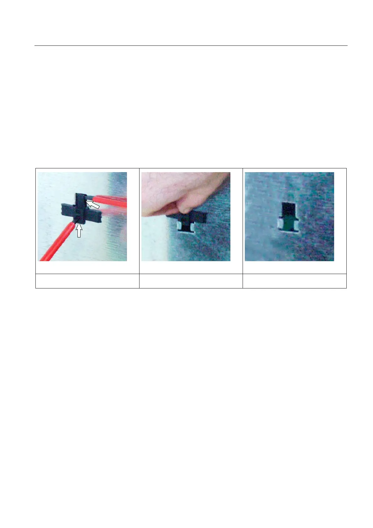
Remove the holder for securing the Control Unit.
Various expansion version make it necessary to remove the plastic retaining element:
If the component to be mounted comes into contact with the lefthand cabinet panel
for a center infeed using Line Modules 55 / 80 / 120 kW
Use suitable tools to lift the latching device
and push up the holder.
Remove the holder. After the removing the holder

Table of Contents

Other manuals for Siemens SINUMERIK 840D sl

Questions and Answers:

Question and Answer IconNeed help?

Do you have a question about the Siemens SINUMERIK 840D sl and is the answer not in the manual?

Siemens SINUMERIK 840D sl Specifications

General IconGeneral
Control TypeCNC
Number of AxesUp to 31
Max Number of Channels10
InterfacesEthernet, PROFIBUS, PROFINET, USB
Interpolation5-axis interpolation
Operating Temperature0°C to 45°C
Relative HumidityUp to 95% (non-condensing)
DisplayTFT color display, various sizes
Programming LanguagesDIN/ISO
Safety FeaturesSafety Integrated
PLCIntegrated PLC S7-300
Drive InterfaceSINAMICS S120
Data StorageCF card, USB
Operating SystemWindows-based

Related product manuals