EasyManuals Logo

Siemens SINUMERIK 840D sl Manual

Siemens SINUMERIK 840D sl
265 pages
To Next Page IconTo Next Page
To Previous Page IconTo Previous Page
Page #23 background imageLoading...
Page #23 background image
Structure of the drive group
2.1 Structure
Guide for the SINUMERIK 840D sl machine configuring
Manual, 07/2006 Edition, 6FC5397-6CP10-0BA0
2-3
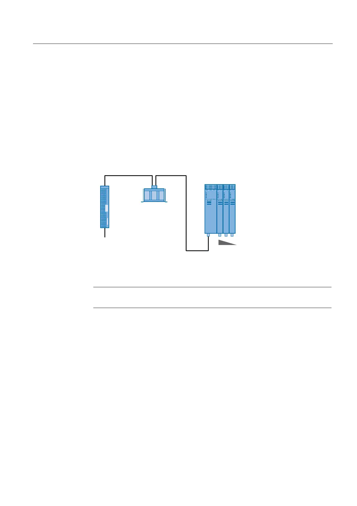
2.1.2 Single row layout
All required components, such as Control Unit and power units are arranged in a row. The
drive group is constructed depending on the available installation location in the control
cabinet and the corresponding general conditions (see above).
The following rule is used as installation rule of the power units from left to right:
Line Module
Motor Modules depending on their power, starting with the highest power and ending with
the lowest power
DC link components, such as Braking Module, Control Supply Module, Capacitor Module
3N:
/LQH
$&9
/LQHILOWHU /LQHFKRNH
/LQH
0RGXOH
0RWRU
0RGXOHV
Figure 2-2 Single row layout
Note
For the layout of the NCU 7x0 or NX1x, see "Layout of the Components"

Table of Contents

Other manuals for Siemens SINUMERIK 840D sl

Questions and Answers:

Question and Answer IconNeed help?

Do you have a question about the Siemens SINUMERIK 840D sl and is the answer not in the manual?

Siemens SINUMERIK 840D sl Specifications

General IconGeneral
Control TypeCNC
Number of AxesUp to 31
Max Number of Channels10
InterfacesEthernet, PROFIBUS, PROFINET, USB
Interpolation5-axis interpolation
Operating Temperature0°C to 45°C
Relative HumidityUp to 95% (non-condensing)
DisplayTFT color display, various sizes
Programming LanguagesDIN/ISO
Safety FeaturesSafety Integrated
PLCIntegrated PLC S7-300
Drive InterfaceSINAMICS S120
Data StorageCF card, USB
Operating SystemWindows-based

Related product manuals