Structure of the drive group
2.1 Structure
Guide for the SINUMERIK 840D sl machine configuring
2-2 Manual, 07/2006 Edition, 6FC5397-6CP10-0BA0
Note concerning the use of components with a width of 50 mm
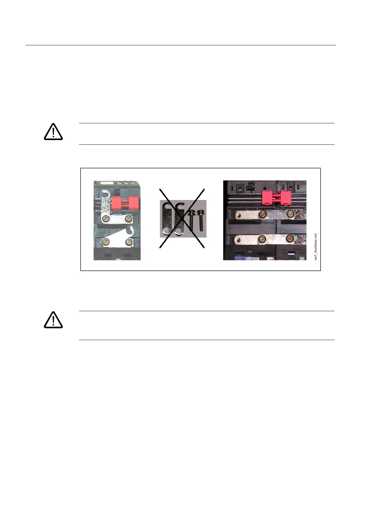
If a 50 mm wide Motor Module or a DC link component of the appropriate width (e.g. Braking
Module, Control Supply Module, Voltage Clamping Module) is located at the left-hand end of
the drive group, the DC link bridge (together with the screws) must be removed.
Danger
The insertion of the screws without the DC link bridge is not permitted.
Figure 2-1 Removal of the DC link bridge
The DC link bridges must be removed by loosening the M4 screws.
Danger
The DC link bridge must not be removed for power units and DC link components (e.g.
Capacitor Module) that are wider than 50 mm.

 Loading...


