Connection of the Components
5.6 Electronics Power Supply
Guide for the SINUMERIK 840D sl machine configuring
5-46 Manual, 07/2006 Edition, 6FC5397-6CP10-0BA0
● A load reserve should be provided; a utilization of 0.7 to 0.8 I
N
is recommended.
● The total length (sum of all cables) of the supply cables for the 24 VDC electronic power
supply between the power supply and the SINAMICS components must not exceed 10
meters.
● The connection cable does not need to be shielded nor twisted. The maximum value of
the ripple voltage, however, must not be exceeded. If this is the case, appropriate
measures must be adopted.
● Where possible, the additional supply for consumers exterior to the SINAMICS system,
such as contactors, valves, etc., should come from a separate power supply. This
reduces any interactions (voltage dips, etc.).
5.6.5 Assignment of the power supply to other components
For Smart/Active Line Module, Motor Module and for the NX component, the supply voltage
is monitored by the system. The components are connected using DRIVE-CLiQ; the
monitoring is performed in the Control Unit.
An integrated 24 VDC busbar is used for the electronic power supply of the
Line/Motor/Braking and Capacitor Modules. The current carrying capacity of this busbar is
max. 20 A. The integrated busbar also supplies the motor brake control terminals of the
Motor Modules.
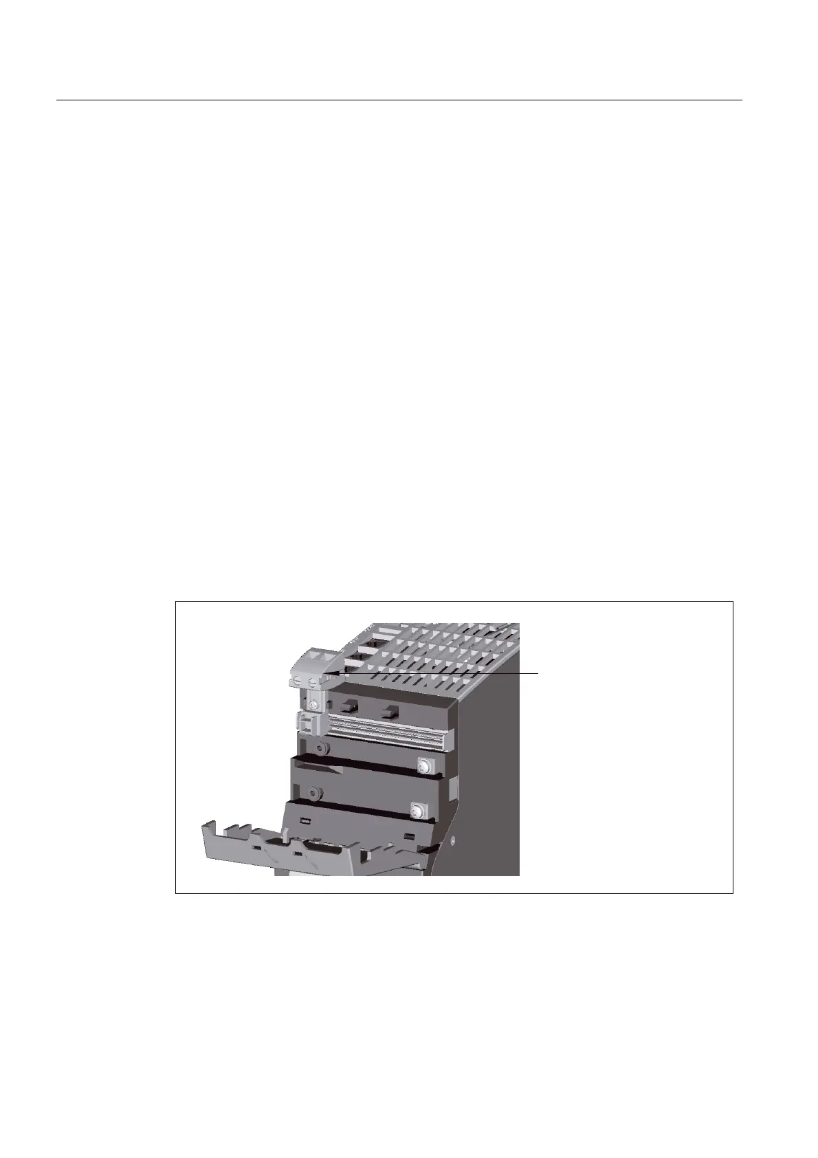
The infeed of the electronic power supply is normally made directly on the Line Module using
the 24 V terminal adapter (max. connectable cross-section 6 mm
2
, max. fuse 20 A) supplied
with the Line Modules.
9WHUPLQDODGDSWHUIRU
FRQGXFWRUFURVVVHFWLRQPP£
Figure 5-18 24 V terminal adapter
The 24 V busbar is used to pass the 24 VDC power between the individual components.
24 V jumper plugs (supplied with the Line Modules) are used to jumper the 24 V busbar at
the component transitions.

 Loading...


