Connection of the Components
5.3 Line Modules Interfaces Description
Guide for the SINUMERIK 840D sl machine configuring
5-26 Manual, 07/2006 Edition, 6FC5397-6CP10-0BA0
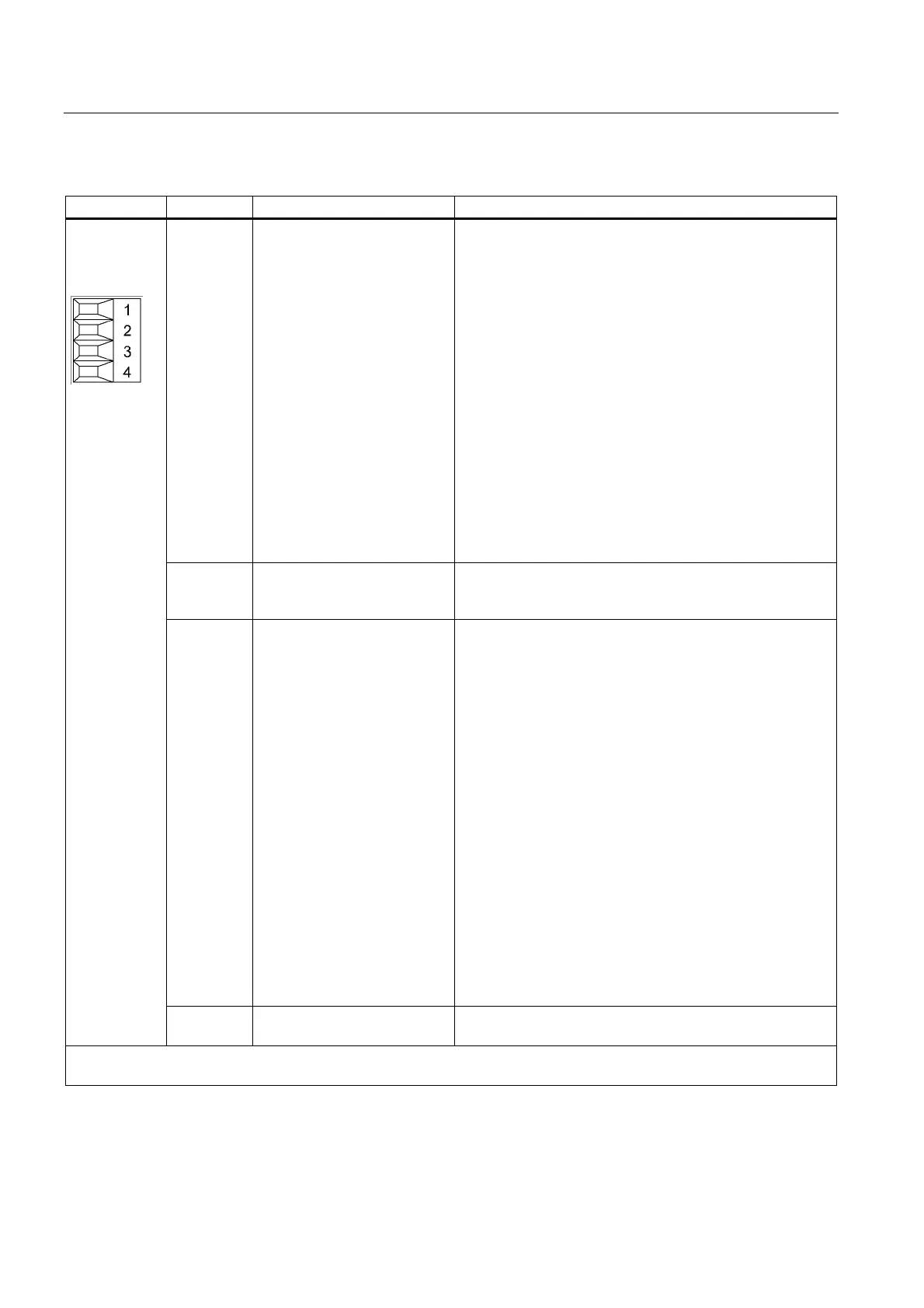
Table 5-8 X21 terminal block
Terminal Designation Technical data
1 DO: Ready Checkback: Smart Line Module ready
The signal switches to high level when the following
conditions have been met:
• Electronics power supply (X24) OK
• DC link is pre-charged
• Enable pulse (X21:3/.4) present
• No overtemperature
• No overcurrent switch-off
Note: Because the Ready signal is cancelled only for fatal
faults, this signal must be processed by the Control Unit or
some other controller and used for the drive group
enable/disable. This must be performed as fast as possible
for the ready cancelation.
Note: All connected actuators, contactor coils, magnetic
valves, holding brakes, etc. must be connected using surge
suppression devices (e.g. diodes, varistors, RC elements,
etc.). This is also true for switchgear/inductances controlled
by a PLC output.
2 Pre Warning DO: Over-temperature prewarning threshold / I x t
High = no prewarning
Low = prewarning
3 DI: Enable pulses
EP +24 V EnablePulses Enable EP control input:
The activation is achieved by placing a 24 VDC voltage
(High level) at the -X21:3 (EP +24 V) terminal.
The supply voltage must be provided from an external
power supply. The -X21:4 (EP M) terminal is used as
reference ground for the external supply voltage.
Disable EP control input:
The disable signal from the Smart Line Module cannot be
set if the EP control input is not enabled (Low level).
Notice:
If the EP control input is disabled, the DC link remains
connected with the supply system voltage using the diode
bridge / precharging resistors. No electrical isolation exists.
If this is to be avoided, a line contactor, for example, can be
used.
Warning:
Before the main power switch is used to switch off the drive
group, the EP function (–X21:3 (+ 24 V) and –X21:4 (M)
connections on the Active Line Module must be disabled,
for example, using a leading (≤ 10 ms) disabling auxiliary
switch on the main power switch.
4 DI: Enable pulses ground
EP M Enable Pulses
Reference potential for the –X21:3 terminal.
Max. connectable cross-section: 1.5 mm
2
Type: Screw terminal 1

 Loading...


