EasyManuals Logo

Siemens SINUMERIK 840D sl Manual

Siemens SINUMERIK 840D sl
265 pages
To Next Page IconTo Next Page
To Previous Page IconTo Previous Page
Page #25 background imageLoading...
Page #25 background image
Structure of the drive group
2.1 Structure
Guide for the SINUMERIK 840D sl machine configuring
Manual, 07/2006 Edition, 6FC5397-6CP10-0BA0
2-5
DC link adapters are used to forward the DC link. Cross-sections of 35 mm² to 95 mm², max.
240 A, can be connected to the connection terminals.
The wiring is performed using single-wire / fine wire and shielded cables and laid short-circuit
and ground-fault safe.
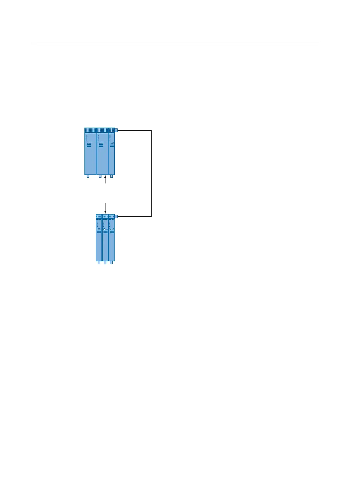
Minimum size for the ventilation clearances for the two-/multi-row construction
&RROLQJFOHDUDQFH
GHSHQGVRQWKHZLGWK
RIWKHFRPSRQHQWV
Figure 2-4 Ventilation clearance for the two-row construction
For components with a width of 50 to 100 mm, the separation between the top and bottom
row must be at least 300 mm.
For components with a width of 150 to 300 mm, the separation between the top and bottom
row must be at least 500 mm.

Table of Contents

Other manuals for Siemens SINUMERIK 840D sl

Questions and Answers:

Question and Answer IconNeed help?

Do you have a question about the Siemens SINUMERIK 840D sl and is the answer not in the manual?

Siemens SINUMERIK 840D sl Specifications

General IconGeneral
Control TypeCNC
Number of AxesUp to 31
Max Number of Channels10
InterfacesEthernet, PROFIBUS, PROFINET, USB
Interpolation5-axis interpolation
Operating Temperature0°C to 45°C
Relative HumidityUp to 95% (non-condensing)
DisplayTFT color display, various sizes
Programming LanguagesDIN/ISO
Safety FeaturesSafety Integrated
PLCIntegrated PLC S7-300
Drive InterfaceSINAMICS S120
Data StorageCF card, USB
Operating SystemWindows-based

Related product manuals