Structure of the drive group
2.6 Heat Dissipation of the Control Cabinet
Guide for the SINUMERIK 840D sl machine configuring
2-24 Manual, 07/2006 Edition, 6FC5397-6CP10-0BA0
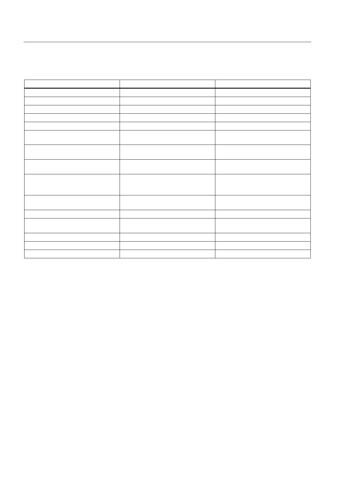
Table 2-2 Ventilation clearances above and below the components
Component Order No. Clearance [mm]
CU320 6SL3040-0MA00-0AAx 80
SMCxx 6SL3055-0AA00-5xAx 50
TM15 6SL3055-0AA00-3FAx 50
TM31 6SL3055-0AA00-3AAx 50
TM41 6SL3055-0AA00-3PAx 50
Line filter for Line Module
5 kW - 120 kW
6SL3000-0BExx-xAAx
100
Line reactor for Active Line Module
16 kW – 120 kW
6SN1111-0AA00-xxAx
100
Line reactor for Smart Line Module
5 kW – 36 kW
6SL3000-0CExx-0AAx
100
Active Line Module
16 kW – 55 kW
80 kW – 120 kW
6SL3130-7TExx-xAAx
6SL3130-7TExx-xAAx
80
80 (additional 50 in front of fan)
Smart Line Module
5 kW – 36 kW
6SL3130-6AExx-0AAx
80
Motor Module < 132 A 6SL312x-1TExx-xAAx 80
Motor Module
132 A and 200 A
6SL312x-1TE3x-xAAx
80 (additional 50 in front of fan)
Braking Module 6SL3100-1AE31-0AAx 80
Control Supply Module 6SL3100-1DE22-0AAx 80
Capacitor Module 6SL3100-1CE14-0AAx 80
The specifications regarding ventilation clearances for two-tier configurations are provided in
Drive Line-Up.

 Loading...


