Configuration
5-44 7SA522 Manual
C53000-G1176-C119-2
5.5 Serial Interfaces
The device contains one or more serial interfaces: an operator interface integrated into
the front panel, and — depending on the model ordered — a rear service interface and
a system interface for connection of a central control system. Certain standards are
necessary for communication via these interfaces, which contain device identification,
transfer protocol, and transfer speed.
Configuration of these interfaces is performed using the DIGSI
®
4 software program.
Click on 6HWWLQJ in the navigation window and double-click in the data window on
,QWHUIDFHV. Next, select the specific data in the resulting dialogue box (Figure 5-
41). The dialogue box contains a varying number of tabs (depending on the capabili-
ties of the PC and the relay) with setting options for the interfaces.
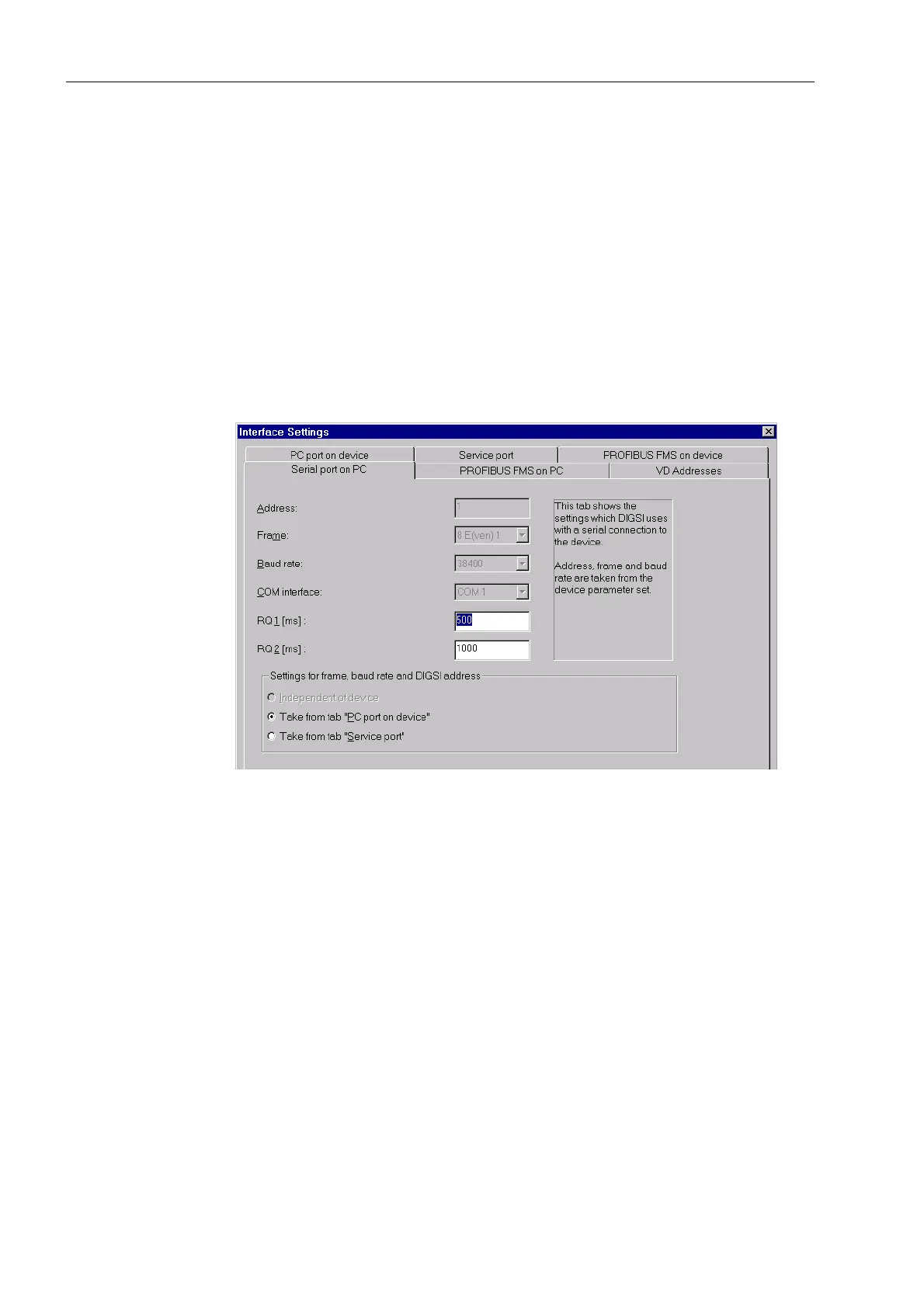
Figure 5-41 DIGSI
®
4, Settings of the PC interface
Serial PC In the first tab, you enter the communication interface of the PC which is connected to
the 7SA522 relay (&20&20 etc.). Manual entry of settings for data format and
baud-rate need not be made if these values were taken from the “GHYLFHIURQW” tab
or the “GHYLFHUHDU” tab (if present). In fact, many settings are read from DIGSI
®
4
directly via the interface, and the corresponding setting fields are then inaccessible
(see Figure 5-41). Alternatively, the option ,QGHSHQGHQWRIGHYLFH may be se-
lected.
Data exchange is monitored by the PC for the reaction times of the device. You may,
within preset limits, configure maximum relay reaction times. The displayed values
RQ 1 and RQ 2 correspond to the preset reaction times in milliseconds. In general,
these values should not be modified. Modification is only necessary if a time-out often
occurs during communication with the device. In order to modify these values, enter
an integer value for RQ 1, between 200 and 9999, and for RQ 2, from 0 to 9999.
Front Port and
Rear Port
Settings for the interfaces at the device can performed in these tabs. The link address-
es and maximum message gap appear in the )URQWSRUW and 5HDUSRUW tab be-
sides the settings for data format and transfer speed (example Figure 5-42).

 Loading...


