Installation and Commissioning
8-337SA522 Manual
C53000-G1176-C119-2
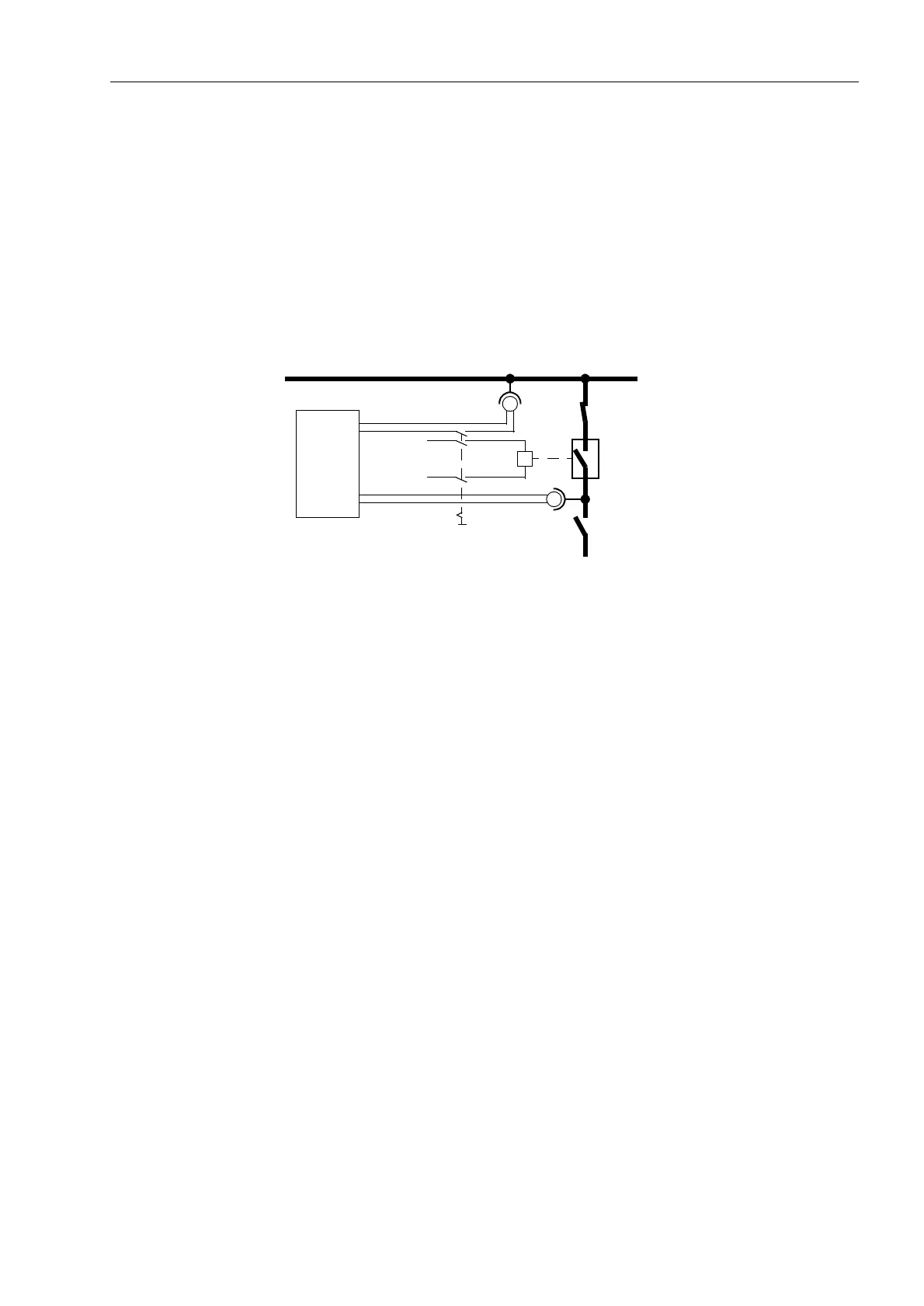
The circuit breaker is connected manually. At the same time the timer is started. After
closing the poles of the circuit breaker, the voltage Uline appears and the timer is
stopped. The time displayed by the timer is the real circuit breaker closing time.
If the timer is not stopped due to an unfavourable closing moment, the attempt will be
repeated.
It is particularly favorable to calculate the mean from several (3 to 5) successful switch-
ing attempts.
Set the calculated time under address as 7&%FORVH (under power system
data 2). Select the next lower adjustable value.
Figure 8-18 Measuring the circuit breaker closing time
8.3.6 Testing of the Teleprotection System
If the device is intended to operate with teleprotection, all devices used for the trans-
mission of the signals must initially be commissioned according to the corresponding
instructions.
8.3.6.1 Teleprotection with Distance Protection
For the functional check of the signal transmission, the earth fault protection should be
disabled, to avoid signals from this protection influencing the tests: address
)&7(DUWK)OW2& = 2)).
Permissive Over-
reach Transfer,
Unblocking
Prerequisite: 7HOHSURWHFWLRQIRU'LVWDQFHSURW7HOHSURW'LVW is
set in address (Section 5.1) to one of the permissive overreach schemes with a
release signal, SHUPLVVLYH RYHUUHDFKor 81%/2&.,1*; furthermore, the param-
eter in address must be set to
)&77HOHS() 21. Naturally, the corresponding send and receive signals must
also be assigned to the corresponding binary output and input. For the echo function,
the echo signal must be assigned separately to the transmit output.
In the case of these release schemes, a simple check of the transmission paths from
one line end is possible using the echo function. The echo function must be activated
at both line ends, i.e. address )&7:HDN,QIHHG = (&+2RQO\; with the set-
ting (&+2DQG75,3 a trip may result at the line end opposite to the test location!
Busbar
U
Line
Feeder
Busbar
L+
L–
Timer
Start
Stop
Close
Voltage

 Loading...


