Installation and Commissioning
8-437SA522 Manual
C53000-G1176-C119-2
8.3.11 Triggering Oscillographic Recordings
At the end of commissioning, an investigation of switching operations of the circuit
breaker(s) or primary switching device(s), under load conditions, should be done to
assure the stability of the protection during the dynamic processes. Oscillographic re-
cordings obtain the maximum information about the behaviour of the 7SA522.
Requirements Along with the capability of recording waveform data during system faults, the 7SA522
also has the capability of capturing the same data when commands are given to the
device via the service program DIGSI
®
4, the serial interfaces, or a binary input. For
the latter, the binary input must be assigned to the function “!7ULJJHU:DYHIRUP
&DSWXUH” (FNo 4). Triggering for the oscillographic recording then occurs when the
input is energized. For example, an auxiliary contact of the circuit breaker or primary
switch may be used to control the binary input for triggering.
An oscillographic recording that is externally triggered (that is, without a protective el-
ement pick-up or device trip) is processed by the device as a normal fault recording
with the exception that data are not given in the fault messages. The externally trig-
gered record has a number for establishing a sequence.
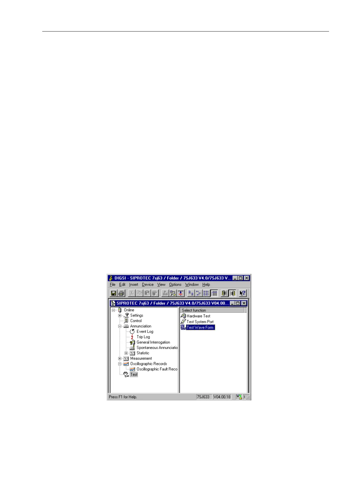
Triggering with
DIGSI
®
4
To trigger oscillographic recording with DIGSI
®
4, click on 7HVW in the left part of the
window. Double click the entry 7HVW:DYH)RUP in the list in the right part of the win-
dow to trigger the recording. See Figure 8-20.
A report is given in the bottom left region of the screen. In addition, message segments
concerning the progress of the procedure are displayed.
The DIGRA
®
program or the Comtrade Viewer program is required to view and ana-
lyse the oscillographic data. Refer to Sub-section 7.1.4.
Figure 8-20 Triggering oscillographic recording with DIGSI
®
4

 Loading...


