Technical Data
10-6 7SA522 Manual
C53000-G1176-C119-2
Optical fibre
– Connector Type ST–connector
for flush mounted case rear panel, mounting location “B”
for surface mounted case on the case bottom
– Optical wavelength λ = 820 nm
– Laser class 1 acc. EN 60825–1/ –2 using glass fibre 50/125 µm or
using glass fibre 62.5/125 µm
– Permissible optical signal attenuation max. 8 dB, using glass fibre 62.5/125 µm
– Maximum transmission distance 1.5 km (0.93 miles)
– Character idle state selectable; factory setting: “Light off”
Time Synchroniza-
tion
– Signal type DCF77/IRIG B-Signal
– Connectionfor flush mounted case rear panel, mounting location “A”
9-pin DSUB socket
for surface mounted case at the terminal on the case bottom
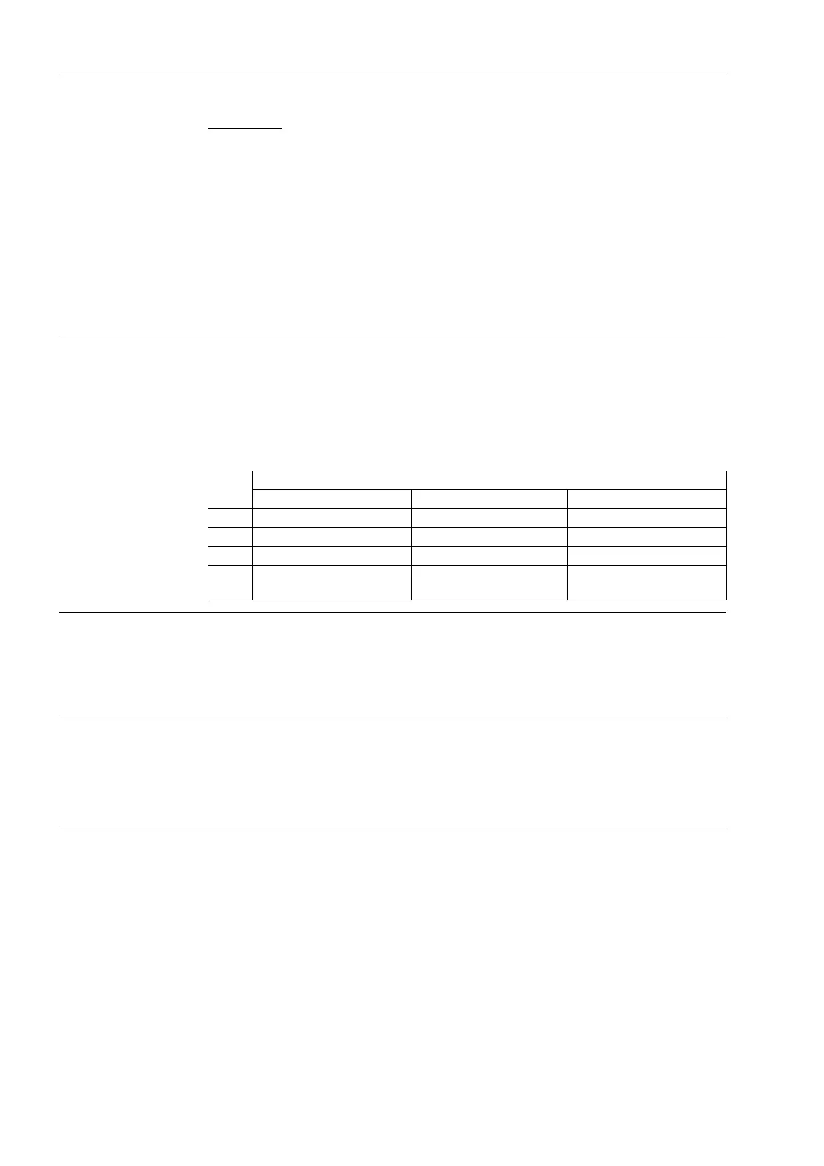
– Nominal signal voltages optional 5 V, 12 V or 24 V
– Signal level and burden:
10.1.5 Electrical Tests
Specifications Standards: IEC 60255 (Product standards)
ANSI/IEEE C37.90.0, C37.90.0.1,
C37.90.0.2
UL 508
DIN 57 435 Part 303
See also standards for individual functions
Insulation Tests Standards: IEC 60255–5 and 60870–2–1
– High voltage test (routine test) 2.5 kV (rms), 50 Hz
all circuits except power supply,
binary inputs, and
communications interfaces
– High voltage test (routine test) 3.5 kVDC
only power supply and binary inputs
– High Voltage Test (routine test) 500 V (rms), 50 Hz
only isolated communications
interfaces
Nominal signal input voltage
5V 12V 24V
U
IHigh
6.0 V 15.8 V 31 V
U
ILow
1.0 V at I
ILow
= 0.25 mA 1.4 V at I
ILow
= 0.25 mA 1.9 V at I
ILow
= 0.25 mA
I
IHigh
4.5 mA to 9.4 mA 4.5 mA to 9.3 mA 4.5 mA to 8.7 mA
R
I
890 Ω at U
I
= 4 V
640 Ω at U
I
= 6 V
1930 Ω at U
I
= 8.7 V
1700 Ω at U
I
= 15.8 V
3780 Ω at U
I
= 17 V
3560 Ω at U
I
= 31 V

 Loading...


