Functions
6-192 7SA522 Manual
C53000-G1176-C119-2
Displacement
Voltage
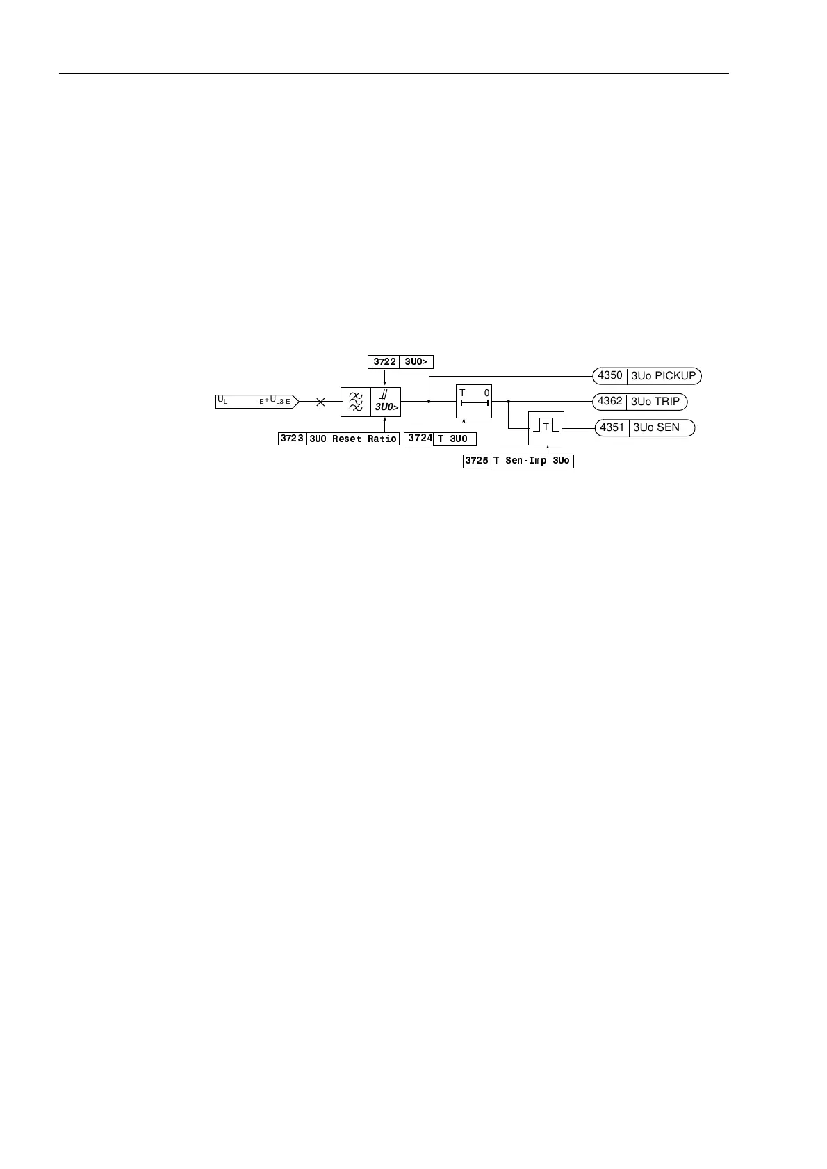
Figure 6-95 shows the logic diagram of the displacement voltage stage. The funda-
mental frequency voltage is filtered out of the measured voltage, so that higher har-
monics and transient voltage peaks are largely suppresses. If the set phase voltage
8! is exceeded, this is alarmed. After expiry of the settable time delay 78 the
trip command is issued. The reset ratio of this stage can be set with the parameter 8
5HVHW5DWLR.
For this stage, the trip command can be transmitted to the other line end or to any oth-
er item of plant as well. The impulse output “8R6(1'”, the duration of which can be
set with the parameter 76HQ,PS82 is used for this purpose.
If the measured voltage supervision “Fuse–Failure–Monitor” has picked up, the dis-
placement voltage protection is automatically blocked.
Figure 6-95 Logic diagram of the zero sequence voltage over voltage protection
Any Single Phase
Voltage
As the function of the displacement voltage stage is separated from the phase voltage
stage it may also be used for any other single-phase voltage, provided that the fourth
voltage measurement input U
4
of the device has been allocated accordingly (refer also
to Section 6.1.1 under “Voltage Transformer Connection”).
6.13.2 Applying the Function Parameter Settings
The overvoltage protection can only operate if it was selected to be (QDEOHG during
the configuration of the scope of functions in the device (refer to Section 5.1, address
).
Phase Voltage
Stage
The phase voltage stage can be switched 21 or 2)) under address . Further-
more, the stage can be set to $ODUP2QO\; i.e. the stage is in service and also issues
alarms, but does not generate any trip commands. The impulse output is however not
suppressed.
The settings for the voltage measurement and the timers depends on the application.
If steady-state overvoltages on long unloaded lines must be detected, the 8SKH!–
stage (address ) is set at least 10 % above the maximum operational steady-
state phase-earth voltage that may arise (the tolerance and reset ratio must be taken
into account). The time delay 78SKH (address ) should be set to several sec-
onds in this case to avoid tripping due to transient overvoltages.
If large overvoltages with short duration must be detected, a larger pick-up threshold
8SKH! (address ) must be set, e.g. 1
1
/
2
–times the nominal phase-earth volt-
age. For the time delay 78SKH (address ) a setting of 0,1 s to 0,2 s should be
sufficient in this case.
8!
3U0>
T0
T
78
76HQ,PS8R
85HVHW5DWLR
U
L1-E
+U
L2-E
+U
L3-E
4350
3Uo PICKUP
4362
3Uo TRIP
4351
3Uo SEND

 Loading...


