Functions
6-877SA522 Manual
C53000-G1176-C119-2
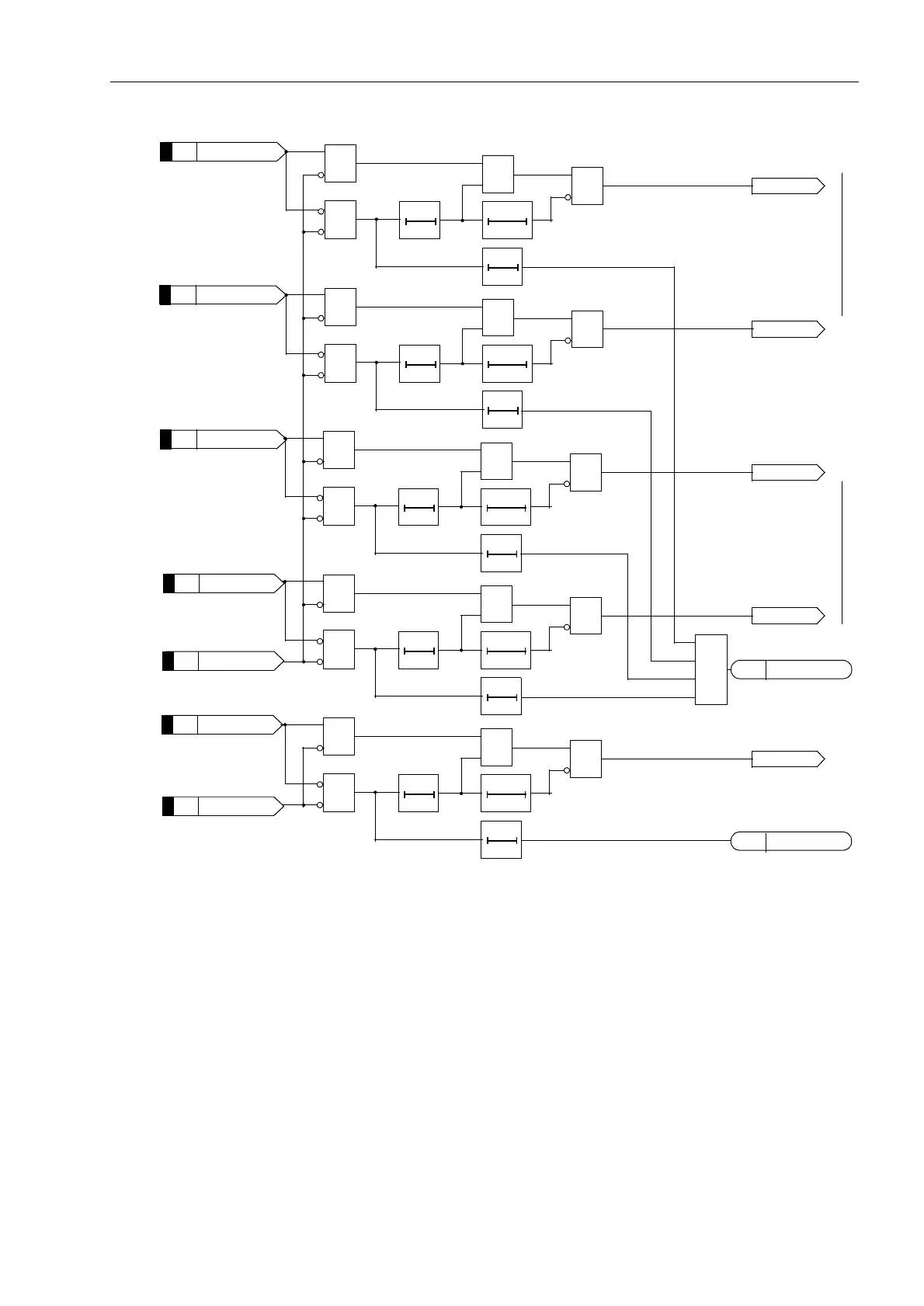
Figure 6-51 Unblock–logic
6.4.1.5 Blocking scheme
Principle The blocking scheme uses the transmission channel to send a block signal from one
line end to the other. The signal may be sent directly after fault inception (jump detec-
tor), and stopped immediately, as soon as the distance protection detects a fault in the
forward direction, alternatively the signal is only sent when the distance protection de-
tects the fault in the reverse direction. The signal will be maintained if the fault is in
reverse direction. If the signal is sent with jump detection (i.e. 'LV-XPS%ORFN
LQJ routed in parallel with - ) only a short delay to allow for signal trans-
mission is required before Z1b trips. A trip can be achieved with this scheme even if
no signal reaches the opposite end. It is therefore mainly used on long lines, when the
signal must be transmitted via the protected line with power line carrier (PLC), and the
>Dis.T.UB ub1L1
&
&
&
020
ms
100100
ms
≥1
Unblock L1
010
s
to receive circuit Figure 6-50to receive circuit Figure 6-50
&
&
&
020
ms
100100
ms
≥1
Unblock L2
010
s
&
&
&
020
ms
100100
ms
≥1
Unblock 1
010
s
Dis.T.UBFail1
&
&
&
020
ms
100100
ms
≥1
Unblock L3
010
s
≥1
&
&
&
020
ms
100100
ms
≥1
Unblock 2
010
s
4032
>Dis.T.UB ub1L2
4033
>Dis.T.UB ub1L3
4034
>Dis.T.UB ub 1
4030
>Dis.T.UB bl 1
4031
>Dis.T.UB ub 2
4035
>Dis.T.UB bl 2
4036
4080
Dis.T.UBFail2
4081

 Loading...


