Functions
6-32 7SA522 Manual
C53000-G1176-C119-2
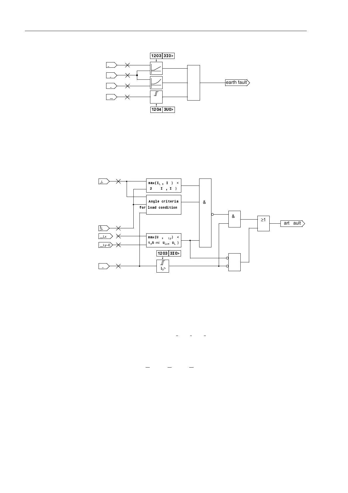
Figure 6-17 Logic of the earth fault recognition.
Earth Fault
Recognition during
Single-Pole Open
Condition
The earth fault recognition is modified during the single-pole open condition with
single-pole automatic reclosure (Figure 6-18). In this case, the magnitudes of the cur-
rents and voltages are monitored in addition to the angles between the currents.
Figure 6-18 Earth fault recognition during single-pole open condition
6.2.1.2 Setting of the Parameters for this Function
In systems with earthed star-point, the setting ,!7KUHVKROG (address ) is
set somewhat below the minimum expected earth short-circuit current. 3I
0
is defined
as the sum of the phase currents |I
L1
+ I
L2
+ I
L3
|, which equals the star-point current
of the set of current transformers.
With regard to the setting 8!7KUHVKROG (address ), care must be taken that
operational unsymmetries do not cause a pick-up. 3U
0
is defined as the sum of the
phase-earth voltages |U
L1–E
+ U
L2–E
+ U
L3–E
|. If the U
0
–criterion should be ignored,
the address is set to ∞.
The preset value usually is sufficient to increase the stabilization of the phase
current ,!,SKPD[ (address ). An increase of the value increases the sta-
bilization.
These settings are summarized with the impedance calculation in a table in Subsec-
tion 6.2.2.2.
3I
0
3I
2 3I
2
≥1
3U
0
3I
0
I
Ph
3I
0
3V0>
I
Ph
,!
8!
earth fault
&
&
≥1
PD[,
Lx
,
Ly
·min(
,
Lx
,
Ly
PD[8
Lx
U
Ly
·min(
8
Lx
8
Ly
$QJOHFULWHULD
3I
0
>
,!
&
3I
0
I
Lx
earthfault
I
Ly
U
Lx–E
U
Ly–E
IRUORDGFRQGLWLRQ

 Loading...


