Functions
6-2217SA522 Manual
C53000-G1176-C119-2
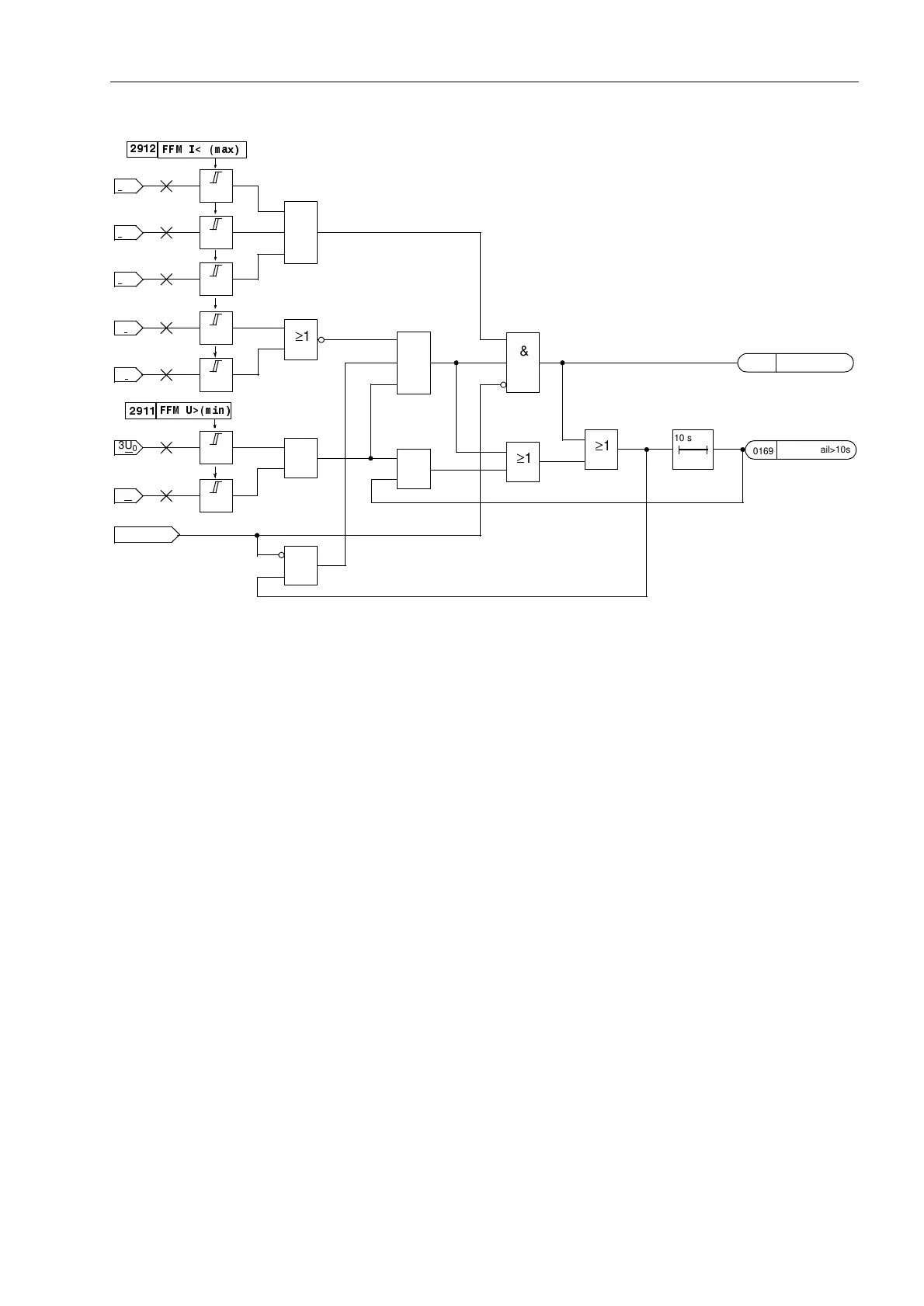
Figure 6-117 Logic diagram of the fuse failure monitor with zero and negative sequence system
Fuse Failure
Monitor
(Three-Phase)
A three-phase failure of the secondary measured voltage can be distinguished from
an actual system fault by the fact that the currents have no significant change in the
event of a failure in the secondary measured voltage. For this reason, the sampled
current values are routed to a buffer, so that the difference between the present and
stored current values can be analysed to recognize the magnitude of the current dif-
ferential (current differential criterion). A three-pole voltage failure is detected if
• all three phase–earth voltages are smaller than the threshold ))08PD[SK,
• the current differential in all three phases is smaller than the threshold
))0,GHOWDS, and
• all three phase current amplitudes are greater than the minimum current ,SK! for
impedance measurement by the distance protection.
If no stored current values are present (yet), the current magnitude criterion is resorted
to. A three-pole system voltage failure is detected in this case if
• all three phase–earth voltages are smaller than the threshold ))08PD[SK,
• all three phase current amplitudes are smaller than the minimum current ,SK! for
impedance measurement by the distance protection, and
• all three phase current amplitudes are greater than a fixed set noise threshold
(40 mA).
If such a voltage failure is recognized, the distance protection and all other functions
that operate on the basis of undervoltage (e.g. also weak infeed tripping) are blocked
until the voltage failure is removed; thereafter the blocking is automatically removed.
Definite time overcurrent emergency operation is possible during the voltage failure if
the overcurrent protection was configured accordingly (refer to Section 6.9).
1pole open
3I
0
3I
2
3U
2
I
L1
I>
I>
U>
I>
U>
I
L2
I>
I
L3
I>
≥1
))0,PD[
3U
0
≥1
≥1
&
≥1
10 s 0
≥1
VT FuseFail
))08!PLQ
≥1
&
&
0170
VT FuseFail>10s
0169

 Loading...


