Configuration
5-41
7SA6 Manual
C53000-G1176-C156-2
Configuration
Sheet
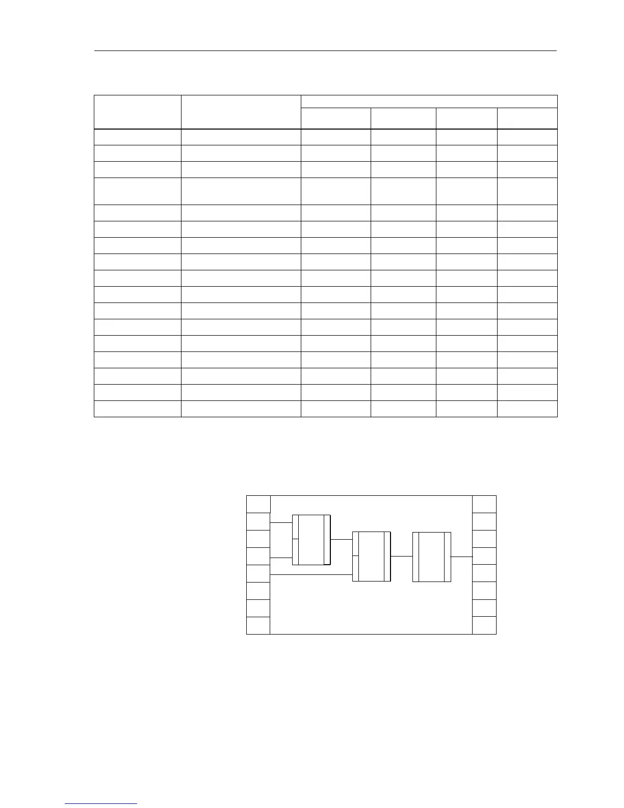
The configuration is performed within the configuration sheets (see Figure 5-36).
Figure 5-36 Principal representation of function modules in a CFC working page
The left border column of the configuration sheet shows the inputs; the right border
column shows the outputs of a function. In the above diagram the inputs are connect-
ed with input signals IS1 to IS3. These may be indications from the breaker (via binary
inputs), from device function keys, or from a protective function. The output signal
CMD_INF Test – – – X
CONNECT Connection – X X X
D_FF D-flipflop – X X X
DI_TO_BOOL Double point to boolean,
conversion
–XXX
LIVE_ZERO Live-zero, non linear curve X – – –
LOWER_SETPOINT Lower limit X – – –
NAND NAND-gate – X X X
NEG Negator – X X X
NOR NOR-gate – X X X
OR OR-gate – X X X
RS_FF RS-flipflop – X X X
SR_FF SR-flipflop – X X X
TIMER Timer – X X –
LONG_TIMER Long timer (max. 1193 h) – X X –
UPPER_SETPOINT Upper limit X – – –
X_OR XOR-gate – X X X
ZERO_POINT Zero suppression X – – –
Table 5-4 Selection guide for function modules and
task levels
Function Modules Description
Run-Time Level
MW_BEARB
Meter processing
PLC1_BEARB
Slow PLC
PLC_BEARB
Fast PLC
SFS_BEARB
Interlocking
IS1
IS2
IS3
OS4
FM2
1
2
3
FM1
1
2
3
FM3
1
2
Configuration sheet 1
Input
signals
Output
signals
Function modules

 Loading...


