Configuration
5-42
7SA6 Manual
C53000-G1176-C156-2
(OS4 in the diagram) may control an output relay, for example, and can create entries
in the message buffers, depending on the preset configuration.
Configuring and
Connecting
Function Modules
The default run-time sequence is determined by the sequence of the insertion of the
logic modules. You may redefine the run-time sequence by pressing <CTRL> – <F11>
on the PC keyboard. Please refer to the CFC manual. The necessary function mod-
ules (FM) are contained in a library located to the right of the configuration chart. The
module also indicates to which of the four run-time levels (MW_BEARB,
PLC1_BEARB, PLC_BEARB, SFS_BEARB) it is assigned. The modules possess at
least one input and one output. In addition to these inputs and outputs, which are dis-
played on the configuration sheet, a module may have additional inputs. The addition-
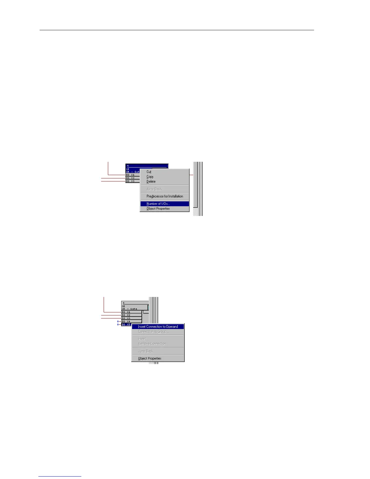
al inputs can be made visible by selecting the module title block, pressing the right
mouse button, selecting the menu option Number Of I/Os... (see Figure
5-37), and then increasing the number.
Figure 5-37 Example of an OR gate: module menu
Under the Object Properties menu, you may edit the name of the module, insert
a comment, or edit run-time properties and connection parameters.
Connecting modules with each other, and linking them with system input and output
signals, is performed by selection of the desired modules input or output and subse-
quently pressing the right mouse button, and selecting the menu option Insert Con-
nection to Operand (see Figure 5-38).
Figure 5-38 Example of module input menu
A window with a list of input signals will appear. By selecting one of these signals and
activating with OK, the selected signal is entered into the left border panel and, from
there, a connection is created to the module input. Selection of an output is done in
the same manner. A connection between two modules is established by a simple se-
quential clicking on the two connections.

 Loading...


