Functions
6-56 7SA6 Manual
C53000-G1176-C156-2
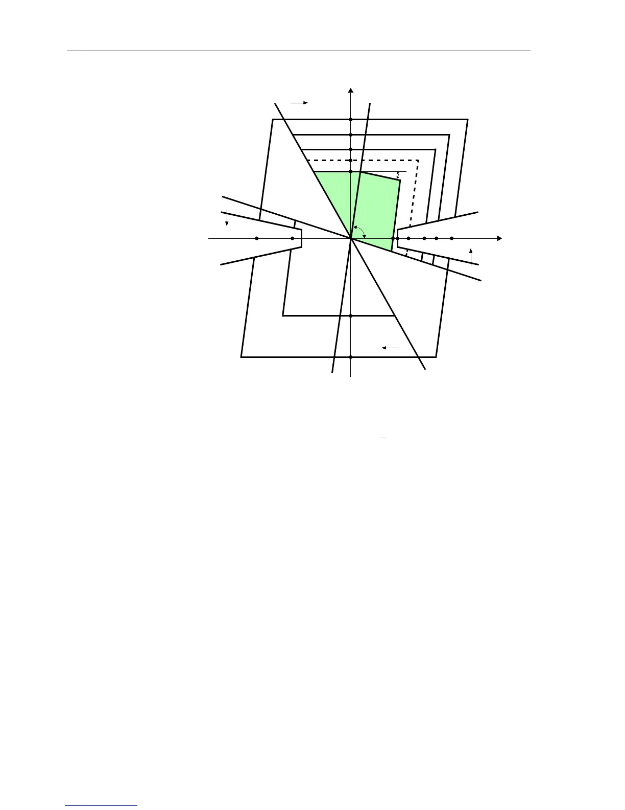
Figure 6-29 Polygonal characteristic
Direction
Determination
For each loop an impedance vector is also used to determine the direction of the short-
circuit. Usually similar to the distance calculation, Z
L
is used. However, depending on
the “quality” of the measured values, different computation techniques are used. Im-
mediately after fault inception, the short circuit voltage is disturbed by transients. The
voltage memorized prior to fault inception is therefore used in this situation. If the
steady-state short-circuit voltage (during a close-in fault) is even too small for direction
determination, an unfaulted voltage is used. This voltage is in theory quadrilateral to
the actual short-circuit voltage for both phase–earth loops as well as for phase–phase
loops (refer to Figure 6-30). This is taken into account when computing the direction
vector by means of a 90°–rotation. In Table 6-9 the allocation of the measured values
to the six fault loops for the determination of the fault direction is shown.
F
o
r
w
a
r
d
α
ϕ
R
e
v
e
r
s
e
R
e
v
e
r
s
e
F
o
r
w
a
r
d
Line Characteristic
Load Area
Load Area
R
X
Z5
Z4
Z2
Z1B
Z3
Z1

 Loading...


