Functions
6-577SA6 Manual
C53000-G1176-C156-2
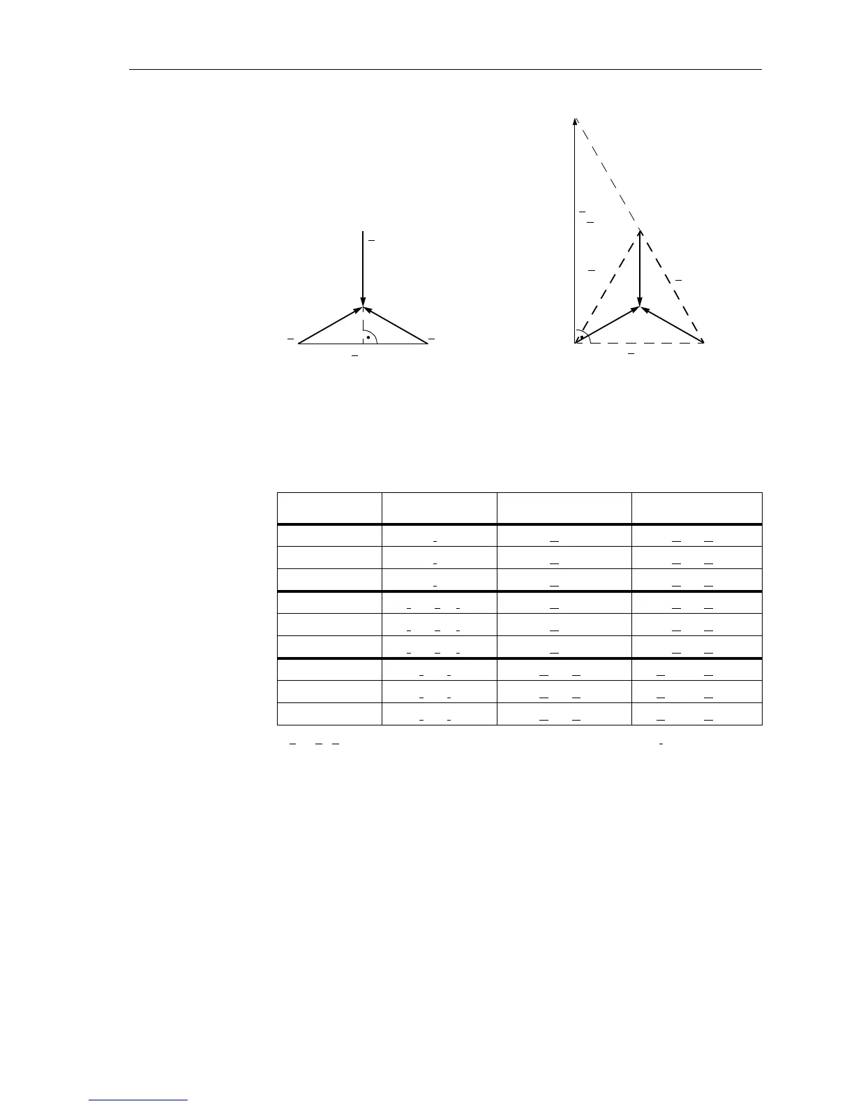
Figure 6-30 Direction determination with quadrature voltages
*) k
E
=Z
E
/Z
L
;ifonlyone phase-earth loop is picked up, the earth current I
E
is considered
If there is neither a current measured voltage nor a memorized voltage available which
is sufficient for measuring the direction, the relay selects the “forward” direction. In
practice this can only occur when the circuit breaker closes onto a de-energized line,
and there is a fault on this line (e.g. closing onto an earthed line).
Figure 6-31 shows the theoretical steady-state characteristic. In practice, the position
of the directional characteristic when using memorized voltages is dependent on both
the source impedance as well as the load transferred across the line prior to fault in-
ception. Accordingly the directional characteristic includes a safety margin with re-
spect to the borders of the first quadrant in the R–X diagram (Figure 6-31).
As each zone may be set
Forward, Reverse or Non-Directional there is a sep-
arate (mirrored) directional characteristic for the “forward” and “reverse” direction.
Table 6-9 Allocation of the measured values for the direction determination
Loop
Measured current
(direction)
Short-circuit loop
voltage
Quadrature
voltage
L1 – E I
L1
U
L1–E
U
L2
–U
L3
L2 – E I
L2
U
L2–E
U
L3
–U
L1
L3 – E I
L3
U
L3–E
U
L1
–U
L2
L1 – E
*
) I
L1
–k
E
·I
E
*
)U
L1–E
U
L2
–U
L3
L2 – E
*
) I
L2
–k
E
·I
E
*
)U
L2–E
U
L3
–U
L1
L3 – E
*
) I
L3
–k
E
·I
E
*
)U
L3–E
U
L1
–U
L2
L1 – L2 I
L1
– I
L2
U
L1
–U
L2
U
L2–L3
–U
L3–L1
L2 – L3 I
L2
– I
L3
U
L2
–U
L3
U
L3–L1
–U
L1–L2
L3 – L1 I
L3
– I
L1
U
L3
–U
L1
U
L1–L2
–U
L2–L3
U
L1
U
L3
U
L2
U
L2–L3
U
L2–L3
U
L1–L2
U
L3–L1
U
L3–L1
–U
L1–L2
a) Phase–earth loop (L1–E) b) Phase–phase loop (L2–L3)

 Loading...


