Functions
6-74 7SA6 Manual
C53000-G1176-C156-2
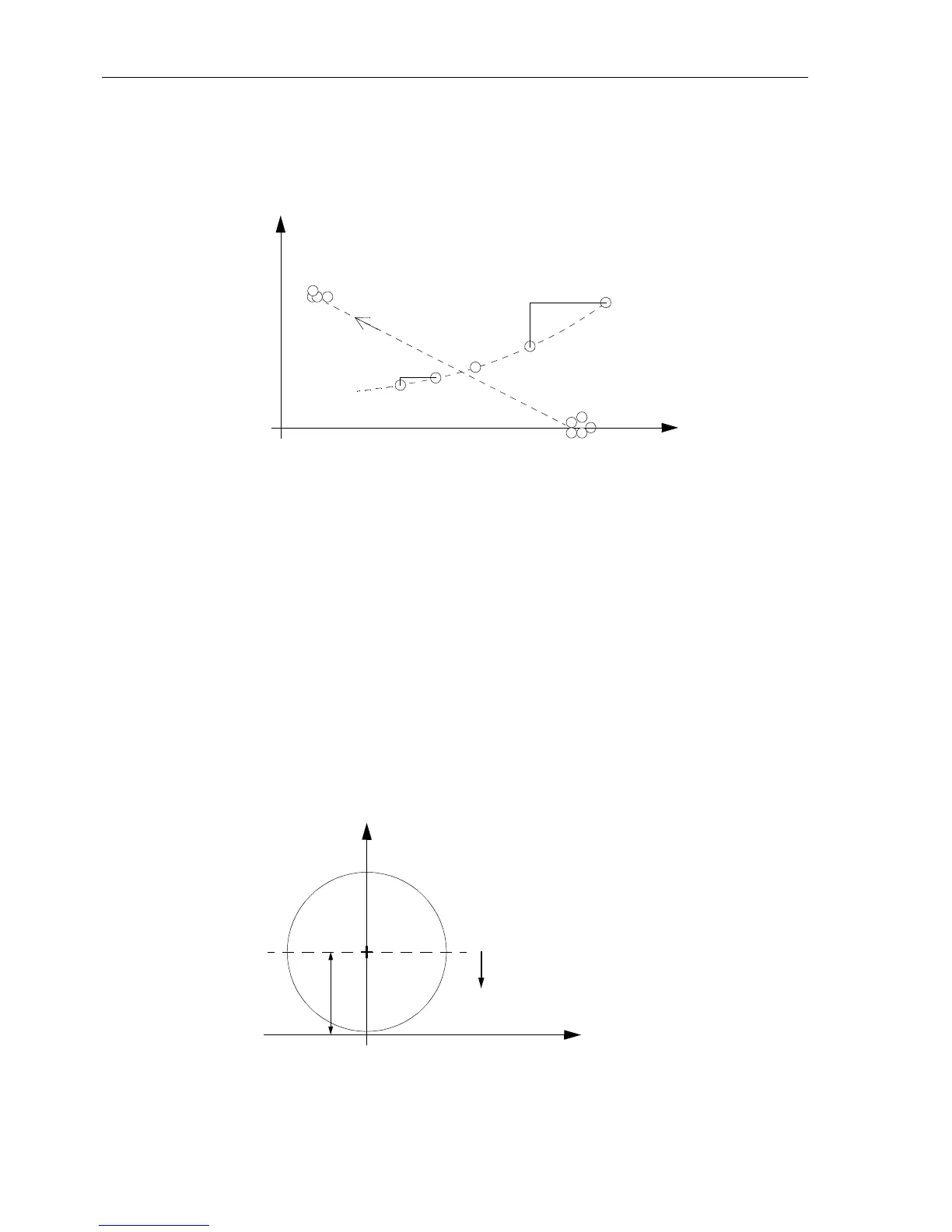
A power swing is detected, if during the last eight measuring cycles (corresponding to
two periods), the continuity of the changing impedance vector is confirmed. In this
way, slip frequencies of up to at least 7 Hz are detected.
Figure 6-41 Impedance vector during power swing
Trajectory
Continuity and
Monotony
The rate of change of the impedance vector is very important for the differentiation
between faults and power swing conditions. In Figure 6-41 this is shown. During the
power swing the measured impedance from one sample to the next has a defined
changeinRandX,referredtoasdR(k)anddX(k).Importantisalsothefactthatfrom
one sample to the next the difference is small: i.e. |dR(k) - dR(k+1)|< threshold.
During a fault entry there is a rapid change that will not cause the power swing function
to pick up.
Trajectory Stability
When the impedance vector enters the impedance characteristic during a
power swing this is on a point of the elliptical curve that corresponds to steady
state instability. For release of the power swing detection a further criterion is
therefor used. In Figure 6-42 the range for steady state instability is shown.
This range is detected in the distance relay by calculating the center of the
ellipse and checking if the actual measured X value is less than this value.
Figure 6-42 Steady state instability range
X
R
Fault
Power swing
Fault entry
Load
impedance
impedance
dX
(k)
dR
(k)
dX
(k-n)
dR
(k-n)
X
R
Steady state
instability range
X
0
-90° +90°
-180°
0°
+180°

 Loading...


