Functions
6-757SA6 Manual
C53000-G1176-C156-2
Trajectory
Symmetry
In addition to these measures, a comparison of the three phases is done to
ensure that they are symmetrical. During a power swing condition in the single
pole open condition only 2 of the three phases will have an impedance
trajectory. In this case only these 2 remaining phase trajectories are checked
to ensure that they are symmetrical.
Power Swing
Detection
To ensure stable and secure operation of the power swing detection without
risking unwanted power swing blocking during power system faults, a logical
combination of a number of measuring criteria are used
.
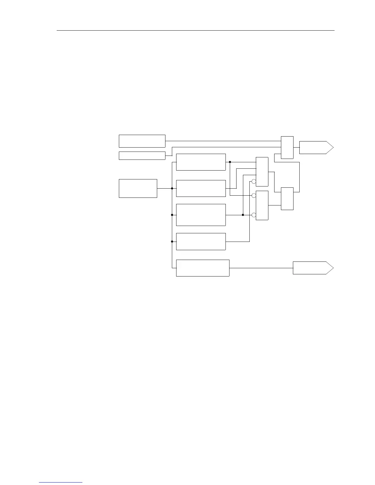
Figure 6-43 Logic diagram of power swing
In Figure 6-43 a simplified logic diagram for the power swing function is given. This
measurement is done on a per phase basis although Figure 6-43 only shows the logic
for one phase. Before a power swing detected signal is generated, the measured
impedance must be inside the power swing polygon (PPOL). A further 4 measuring
criteria must be fulfilled.
G Trajectory continuity
ThemeasuredRandXvaluesmustdescribeasteadypathwithoutajumpfromone
measured value to the next. Refer to Figure 6-41.
G Trajectory monotony
The impedance trajectory must initially not change R-direction. Refer to
Figure 6-41.
G Trajectory symmetry
The trajectory of each phase is evaluated. If no fault is present these 3 trajectories
must be symmetrical. During single pole open conditions the remaining 2
trajectories must be symmetrical.
No trip output
Trajectory continuity
No jump of R-values
and X-values
present
Trajectory symmetry
Check symmetry of
trajectories that may
Impedance in PPOL
SQ
Trajectory monotony
No change in R-direction
Trajectory stability
Calculate centre of
trajectory
&
&
R
Power swing
detected
Trajectory check OST
Check sign of R when fault
enters and exits zone
Change
of sign
Outofstep
protection trip
R, X
3
Calculation of
the R und X
&
values
be swinging

 Loading...


