Functions
6-228 7SA6 Manual
C53000-G1176-C156-2
J
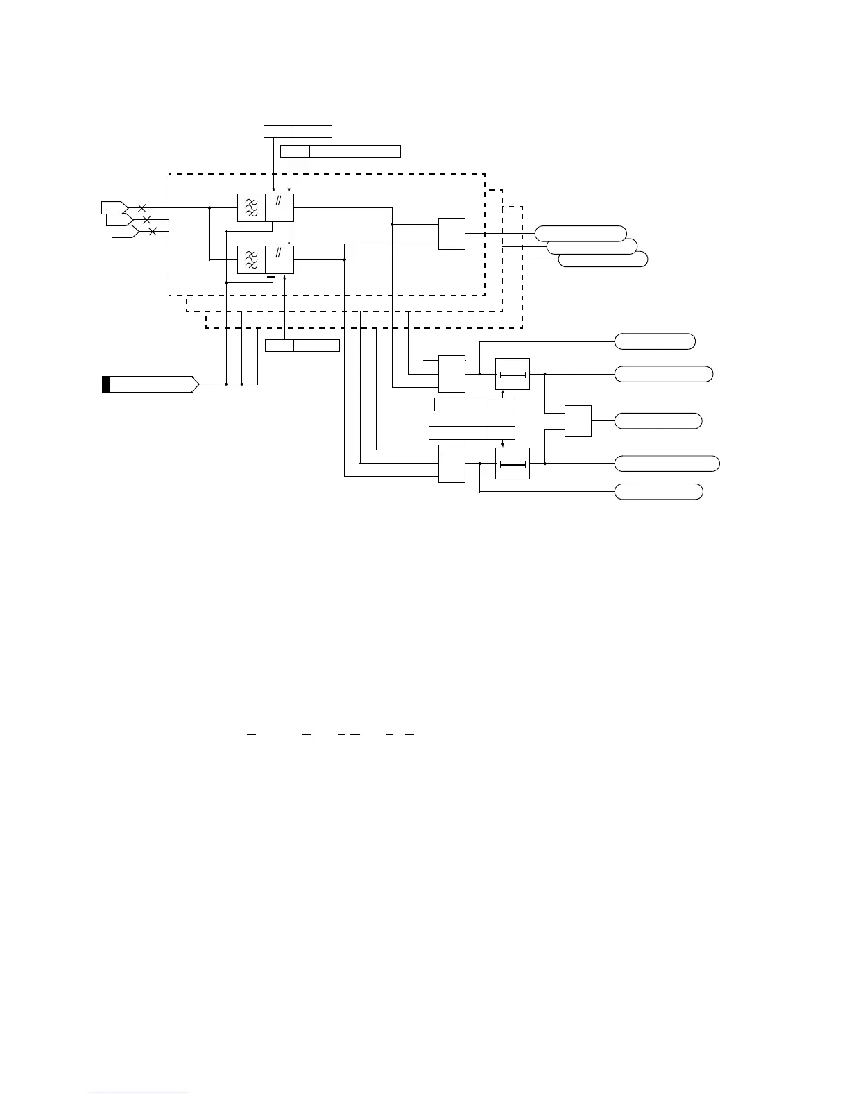
Figure 6-114 Logic diagram of the overvoltage protection for phase voltages
Overvoltage
Phase–Phase
The phase–phase overvoltage protection operates just like the phase–earth protec-
tion except that it detects phase–to–phase voltages. Accordingly, phase–to–phase
voltages which have exceeded one of the stage thresholds
Uph-ph> or Uph-ph>>
are also indicated. Otherwise, Figure 6-114 also applies in principle.
The phase–phase overvoltage protection can also be blocked via a binary input
“
>Uph-ph>(>) BLK”.
Overvoltage
Positive Sequence
System U
1
The device calculates the positive sequence system voltage according to its defining
equation:
U
1
=
1
/
3
⋅(U
L1
+a⋅U
L2
+a
2
⋅U
L3
)
with a
=e
j120°
.
The resulting single–phase AC voltage is fed to the two threshold stages
U1> and
U1>> (see Figure 6-115). Combined with the associated time delays these stages
form a two-stage overvoltage protection for the positive sequence system. Here too,
the drop-off to pick-up ratio can be set.
The overvoltage protection for the positive sequence system can also be blocked via
a binary input “
>U1>(>) BLK”.
U
L3-E
U
L2-E
U
L1-E
U>
3702 Uph–e>
T0
3703T Uph–e>
T Uph-e> TimeOut
Uph-e> Pickup
L1
U>>
3709 Uph–e>(>) RESET
≥1
≥1
T0
3705T Uph–e>>
T Uph-e>> TimeOut
Uph-e>> Pickup
≥1
Uph-e>(>) TRIP
≥1
Uph-e>(>) PU L3
Uph-e>(>) PU L2
Uph-e>(>) PU L1
L2
L3
3704 Uph–e>>
>Uph-e>(>) BLK
FNo 10201
FNo10242to10244
FNo 10240
FNo 10241
FNo 10245
FNo 10247
FNo 10246

 Loading...


