Functions
6-2297SA6 Manual
C53000-G1176-C156-2
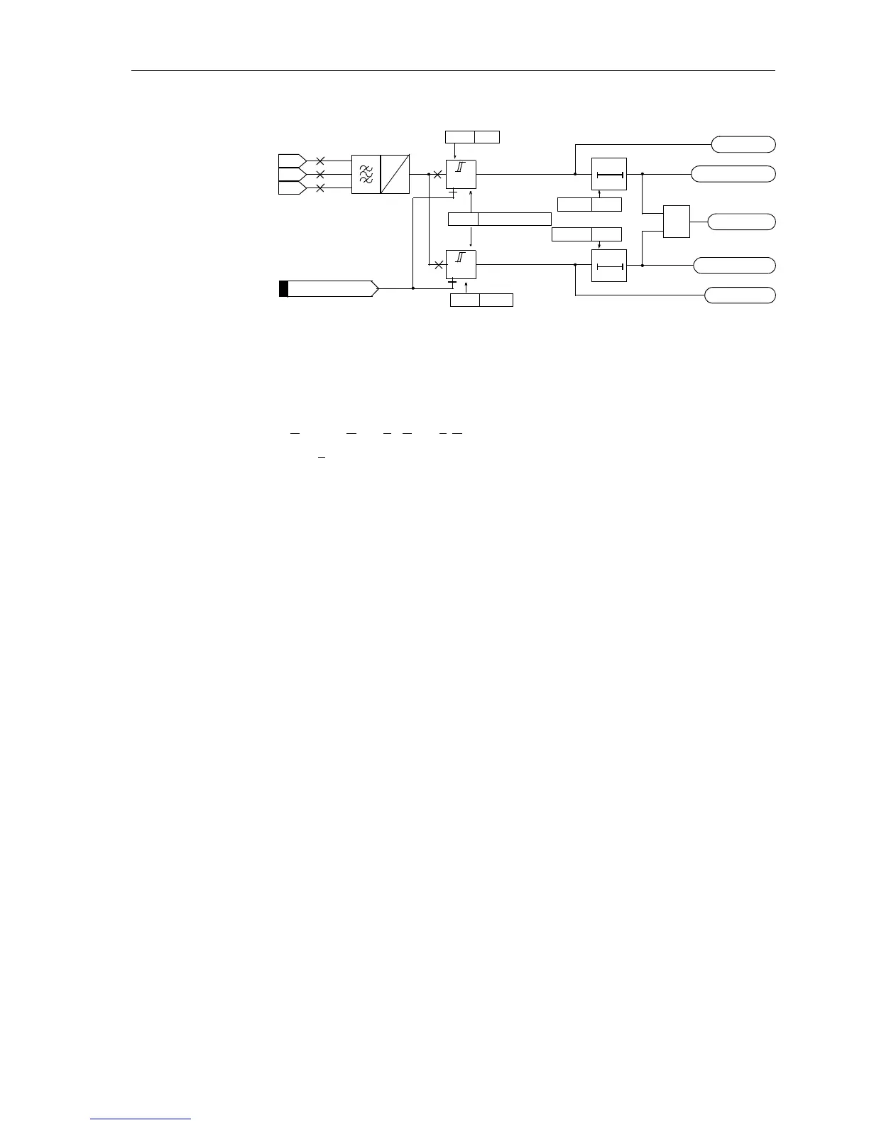
Figure 6-115 Logic diagram of the overvoltage protection for the positive sequence
voltage system
Overvoltage
Negative Sequence
System U
2
The device calculates the negative sequence system voltages according to its defining
equation:
U
2
=
1
/
3
⋅(U
L1
+a
2
⋅U
L2
+a⋅U
L3
)
with a
=e
j120°
.
The resulting single–phase AC voltage is fed to the two threshold stages
U2> and
U2>>. The logic is designed just like in the positive sequence system (Figure 6-115).
Combined with the associated time delays
T U2> and T U2>> these stages form a
two-stage overvoltage protection for the negative sequence system. Here too, the
drop-off to pick-up ratio can be set. The overvoltage protection for the negative se-
quence system can also be blocked via a binary input “
>U2>(>) BLK”. The stages of
the negative sequence voltage protection are automatically blocked as soon as an
asymmetrical voltage failure was detected (“Fuse–Failure–Monitor”, also see Section
6.21.1.3, margin heading “Fuse Failure Monitor (Non-Symmetrical Voltages)”) or
whenthetripofthemcbforvoltagetransformershasbeensignalledviathebinaryin-
put “
>FAIL:Feeder VT” (internal indication “internal blocking”).
The stages of the negative sequence voltage protection are automatically blocked
(with the internal automatic reclosure function) during single-pole automatic reclose
dead time, to avoid pick-up with the false negative sequence values arising during this
state. If the device cooperates with an external automatic reclosure function, or if a sin-
gle-pole tripping can be triggered by a different protection system (working in parallel),
the overvoltage protection for the negative sequence system must be blocked via a
binary input during single-pole tripping.
Overvoltage
Zero Sequence
System 3⋅U
0
Figure 6-116 depicts the logic diagram of the zero sequence voltage stage. The fun-
damental frequency is numerically filtered from the measuring voltage so that the har-
monics or transient voltage peaks remain largely harmless.
The triple zero sequence voltage 3 U
0
is fed to the two threshold stages 3U0> and
3U0>>. Combined with the associated time delays T 3U0> and T 3U0>> these stag-
es form a two-stage overvoltage protection for the zero sequence system. Here too,
the drop-off to pick-up ratio can be set (
3U0>(>) RESET).
The overvoltage protection for the zero voltage system can also be blocked via a bi-
nary input “
>3U0>(>) BLK”. The stages of the zero sequence voltage protection are
automatically blocked as soon as a asymmetrical voltage failure is detected (“Fuse–
Failure–Monitor”, also see Section 6.21.1.3, margin heading “Fuse Failure Monitor
(Non-Symmetrical Voltages)”) or if the trip of the mcb for voltage transformers has
U
L3-E
U
L2-E
U
L1-E
U>
3732 U1>
T0
3733T U1>
TU1>TimeOut
U1> Pickup
U>>
3739 U1>(>) RESET
T0
3735T U1>>
T U1>> TimeOut
U1>> Pickup
U1>(>) TRIP
≥1
3734 U1>>
>U1>(>) BLK
U
1
U
Ph–E
FNo 10204
FNo 10280
FNo 10282
FNo 10284
FNo 10283
FNo 10281

 Loading...


