Functions
6-232 7SA6 Manual
C53000-G1176-C156-2
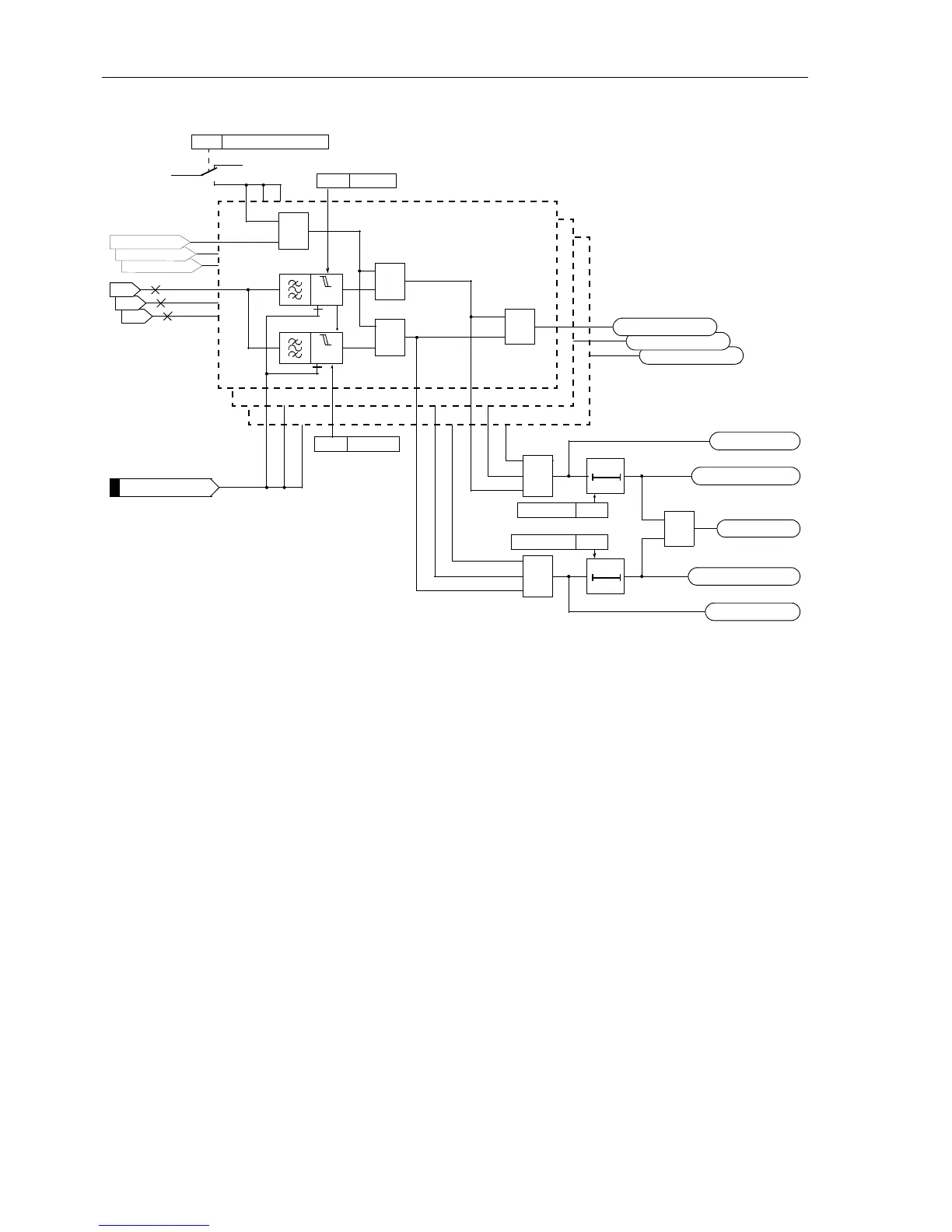
Figure 6-117 Logic diagram of the undervoltage protection for phase voltages
Undervoltage
Phase–Phase
Basically, the phase–phase undervoltage protection operates like the phase–earth
protection except that it detects phase–to–phase voltages. Accordingly, both phases
are indicated during pick-up of an undervoltage stage if one of the stage thresholds
Uph-ph< or Uph-ph<< was undershot. Beyond this, Figure 6-117 applies in princi-
ple.
It is sufficient for the current criterion that current flow is detected in one of the involved
phases.
The undervoltage protection phase–phase can also be blocked via a binary input
“
>Uphph<(<) BLK”. There is an automatic blocking if the measuring voltage failure
was detected or voltage mcb tripping was indicated (internal blocking of the phases
affected by the voltage failure).
During single-pole dead time for automatic reclosure (using the internal automatic re-
closure function) the stages of the undervoltage protection are automatically blocked
in the disconnected phase so that it does not respond to the undervoltage of the dis-
connected phase provided that the voltage transformers are located on the outgoing
side.
I–REST> L3
I–REST> L2
U
L3-E
U
L2-E
U
L1-E
3752 Uph–e<
T0
3753T Uph–e<
T Uph-e< TimeOut
Uph-e< Pickup
L1
≥1
≥1
T0
3755T Uph–e<<
T Uph-e<<TimeOut
Uph-e<< Pickup
≥1
Uph<(<) TRIP
≥1
Uph-e<(<) PU L3
Uph-e<(<) PU L2
Uph-e<(<) PU L1
L2
L3
3754 Uph–e<<
>Uph-e<(<) BLK
3758
ON
OFF
CURR.SUP. Uphe<
I–REST> L1
„1“
&
≥1
&
U<
U<<
FNo 10206
FNo 10312 to 10314
FNo 10310
FNo 10315
FNo 10317
FNo 10316
FNo 10311

 Loading...


