Functions
6-2337SA6 Manual
C53000-G1176-C156-2
Undervoltage
Positive Sequence
System U
1
The device calculates the positive sequence system according to its defining equation
U
1
=
1
/
3
⋅(U
L1
+a⋅U
L2
+a
2
⋅U
L3
)
with a
=e
j120°
.
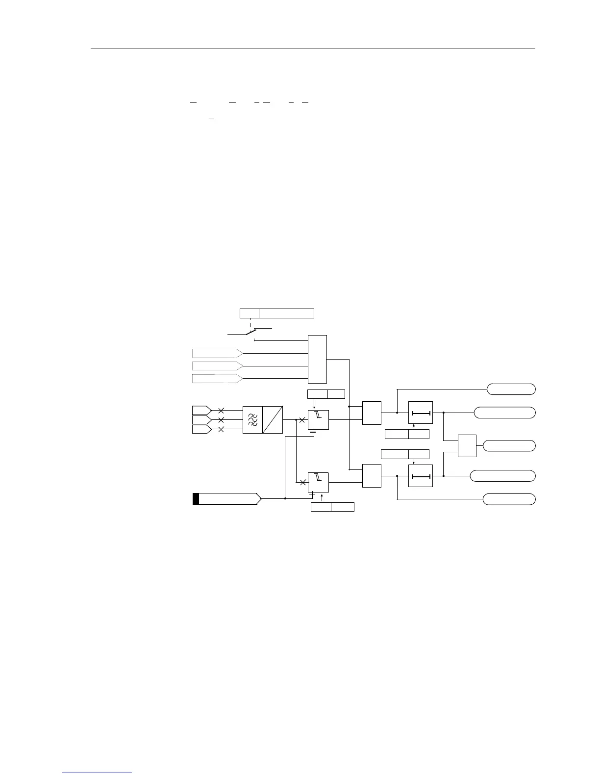
The resulting single–phase AC voltage is fed to the two threshold stages
U1< and
U1<< (see Figure 6-118). Combined with the associated time delays T U1< and T
U1<<
these stages form a two-stage undervoltage protection for the positive se-
quence system.
Current can be used as an additional criterion for the undervoltage protection of the
positive sequence system (current supervision
CURR.SUP.). An undervoltage is only
detected if the current flow is detected in at least one phase together with the under-
voltage criterion.
The undervoltage protection for the positive sequence system can be blocked via the
binary input “
>U1<(<) BLK”. The stages of the undervoltage protection are automat-
ically blocked if voltage failure is detected (“Fuse–Failure–Monitor”, also see Section
6.21.1.3) or, if the trip of the mcb for the voltage transformer is indicated via the binary
input “
>FAIL:Feeder VT” (internal blocking).
Figure 6-118 Logic diagram of the undervoltage protection for positive sequence voltage sys-
tem
During single-pole dead time for automatic reclosure (using the internal automatic re-
closure function) the stages of the undervoltage protection are automatically blocked
in the positive sequence system so that they do not respond to the reduced voltage
cause by the disconnected phase in case the voltage transformers are located on the
outgoing side.
U
L3-E
U
L2-E
U
L1-E
U<
3772 U1<
T0
3773T U1<
TU1<TimeOut
U1< Pickup
U<<
T0
3775T U1<<
T U1<< TimeOut
U1<< Pickup
U1<(<) TRIP
≥1
3774 U1<<
>U1<(<) BLK
U
1
U
Ph–E
3778
ON
OFF
CURR.SUP.U1<
„1“
&
&
I–REST> L3
I–REST> L2
I–REST> L1
≥1
FNo 10208
FNo 10300
FNo 10302
FNo 10304
FNo 10303
FNo 10301

 Loading...


