Installation and Commissioning
8-297SA6 Manual
C53000-G1176-C156-2
Input/Output Board
C–I/O–2
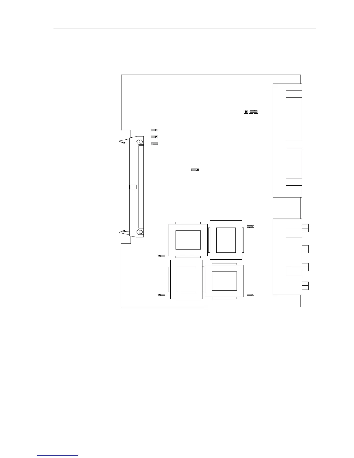
The layout of the printed circuit board for the input/output board C-I/O–2 is illustrated
in Figure 8-16.
Figure 8-16 The input/output board C-I/O–2 with the jumpers necessary for the setting
check
The contact of the relay for the binary output BO6 can be configured as NO or NC con-
tact (see also General Diagrams in Appendix A, Section A.2).
Mounting location:
for housing size
1
/
3
in Figure 8-9, slot 19,
for housing size
1
/
2
in Figure 8-10, slot 33,
for housing size
1
/
1
in Figure 8-11, slot 33 right.
X61
1A
5A
3
2
1
T8
T6
T7
T5
X64
1A
5A
3
2
1
X63
5A
1A
1
2
3
X62
5A
1A
1
2
3
X60
1A
5A
3
2
1
X41
1
3
2
(AD0)
L
X71
1
2
3
(AD1)
X72
1
2
3
(AD2)
X73
H

 Loading...


